5
Measuring current
The current drawn by the nRF9160 can be monitored on the nRF9160 DK.
Current can be measured using various test instruments. Examples of test equipment are the following:
• Power analyzer
• Oscilloscope
• Ampere-meter
Connector P24 can be used for measuring current consumption or monitoring voltage levels to the
nRF9160.
The use of a USB connector is not recommended for powering the board during current measurements
due to potential noise from the USB power supply. Instead, the board should be powered by connecting a
power supply to connector P28.
For more information on measuring, see sections Using an oscilloscope for current profile measurement
on page 37 and Using a current meter for current measurement on page 37.
5.1 Preparing the development kit for current
measurements
To measure the current consumption of the SiP, you must first prepare the board.
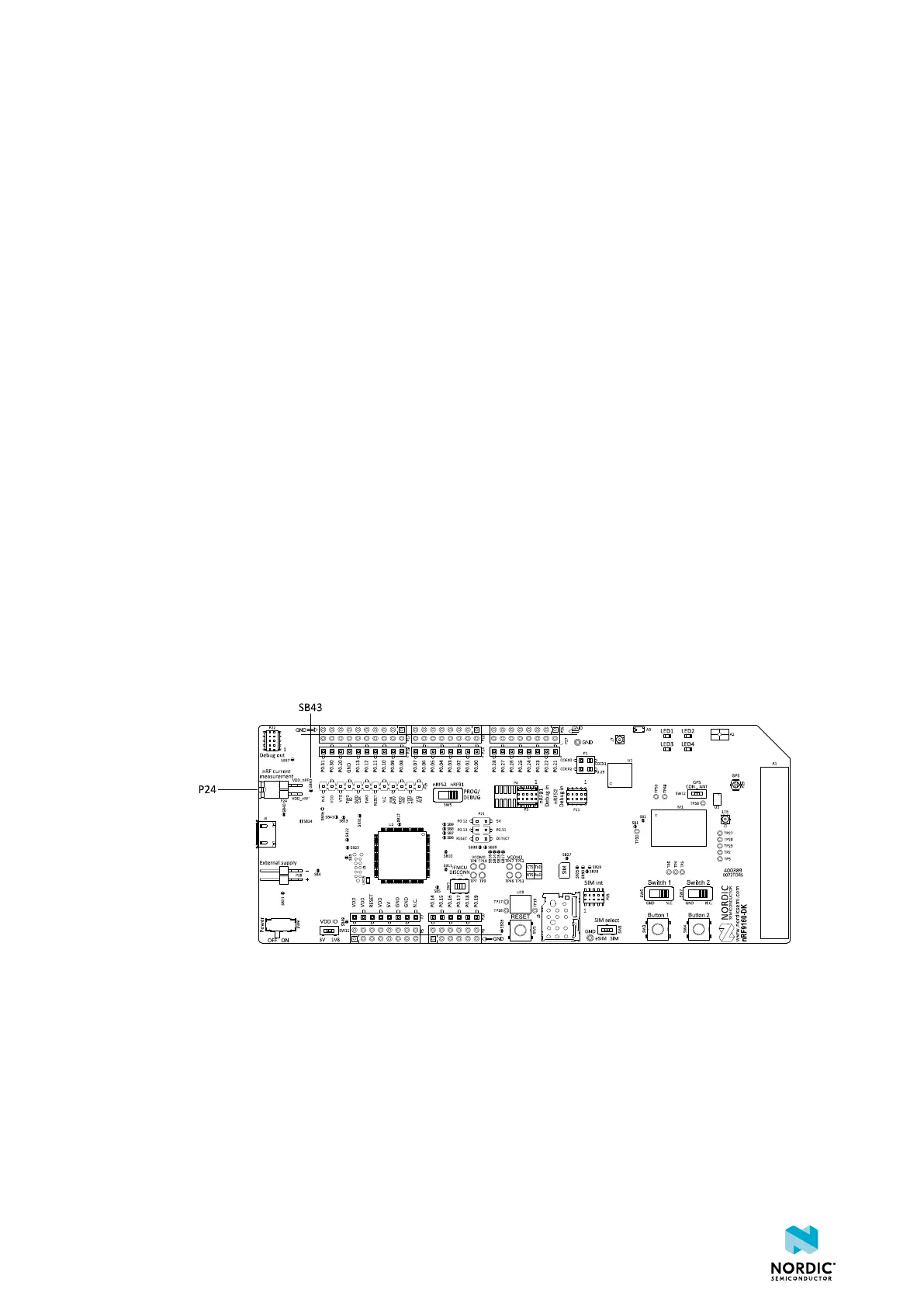
1. Remove jumper from P24.
Removing the jumper disconnects the nRF9160 from the power management circuitries on the board.
Figure 28: Solder bridge SB43 and P24 on the nRF9160 DK board
2. To restore normal kit functionality after measurement, apply the jumper on P24 or short SB43.
4418_1216 v0.9.1
36
 Loading...