Hardware description
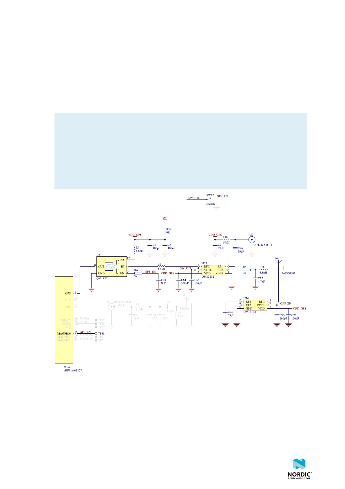
The onboard antenna can be disconnected and an external GPS antenna enabled by attaching the external
GPS antenna to connector P29 and sliding switch SW12 to CON position. 3.0 V DC is fed through P29 to
supply an external LNA, if desired. The external GPS antenna can be connected to connector P29 (Hirose
part no. U.FL-R-SMT-1). A compatible adapter cable is required to connect a GPS antenna to the DK.
Switch U34 and the combined LNA and BPF are enabled by the GPS-enable signal from the nRF9160.
The signal is next amplified and filtered in the LNA and BPF U3 before it is fed to the nRF9160. This makes
the GPS receiver more sensitive to GPS signals and less sensitive to interference from other sources on the
DK or nearby.
Note:
• GPS signals do not usually penetrate ceilings or other structures that well. Therefore, for best
GPS performance, the DK should be placed on a flat surface in an open space outside, far from
sources of interference and other structures that may block the signals from space.
• This functionality is only available if the modem firmware used in the nRF9160 supports GPS.
• The Molex patch antenna achieves the highest gain when placed horizontally on a surface (x-y)
facing the z-axis since it can receive all propagated GPS signals. A lower gain will be experienced
if the patch antenna is mounted on a surface is at an angle with the horizontal surface.
Figure 12: GPS connected to the nRF9160
4.6 GPIO interfaces
Access to the nRF9160 GPIOs is available from connectors P7, P10, P14, P19, and P27. The nRF9160 DK
supports the Arduino UNO interface.
4418_1216 v0.9.1
18
 Loading...