Installation
A1-25
E 2000 Nordson Corporation
All rights reserved
41-3000V
Issued 5/00
A3EN-04-[3V-A-AAXP]-12
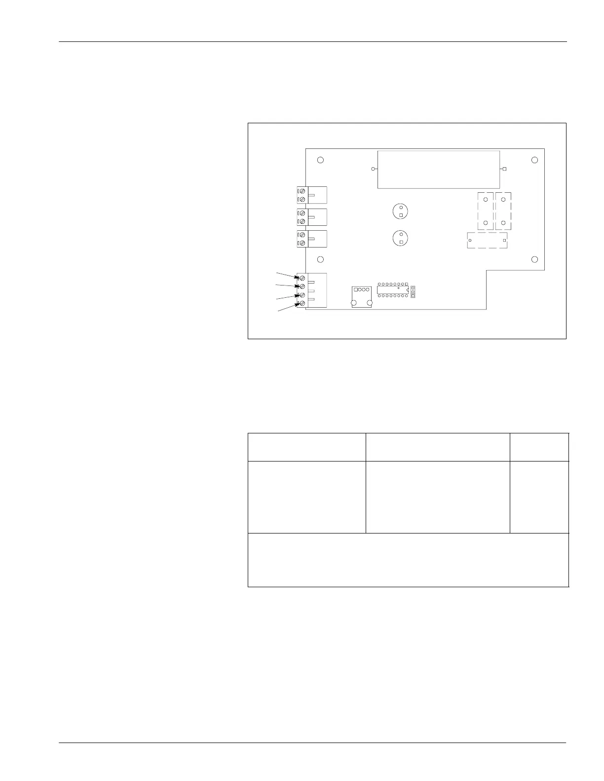
6. See Figure A 1-15. The trigger device, usually a photosensor, and
the enable/disable devices are connected at terminal block X6P on
the pattern control driver board. To connect these devices, refer to
Table A 1-4.
4130254
X6P
1
2
3
4
Fig. A 1-15 Terminal Block X6P on the Pattern Control Driver Board
1. Position 1
2. Position 2
3. Position 3
4. Position 4
Table A 1-4 Connections for T rigger and Enable/Disable Devices
Functional Description
Position on Terminal Block
X6P
Note
+15V 1
trigger 2 A
common 3 B
enable/disable 4 B
NOTE A: The driver board accepts either a current-sourcing or a
current-sinking trigger input.
B: If you are not using a remote enable/disable device, install a
jumper wire between positions 3 and 4.
 Loading...


