Installation
A1-24
E 2000 Nordson Corporation
All rights reserved
41-3000V
Issued 5/00
A3EN-04-[3V-A-AAXP]-12
3. Route the wiring from the following devices into the electrical
enclosure.
S trigger devices
S each gun solenoid valve (or other gun driver device)
S remote enable/disable device (if used)
WARNING: Risk of electrical shock or equipment damage.
Failure to install ferrites as shown can result in equipment
damage, personal injury, or death. Ferrites must not come into
contact with an energized component.
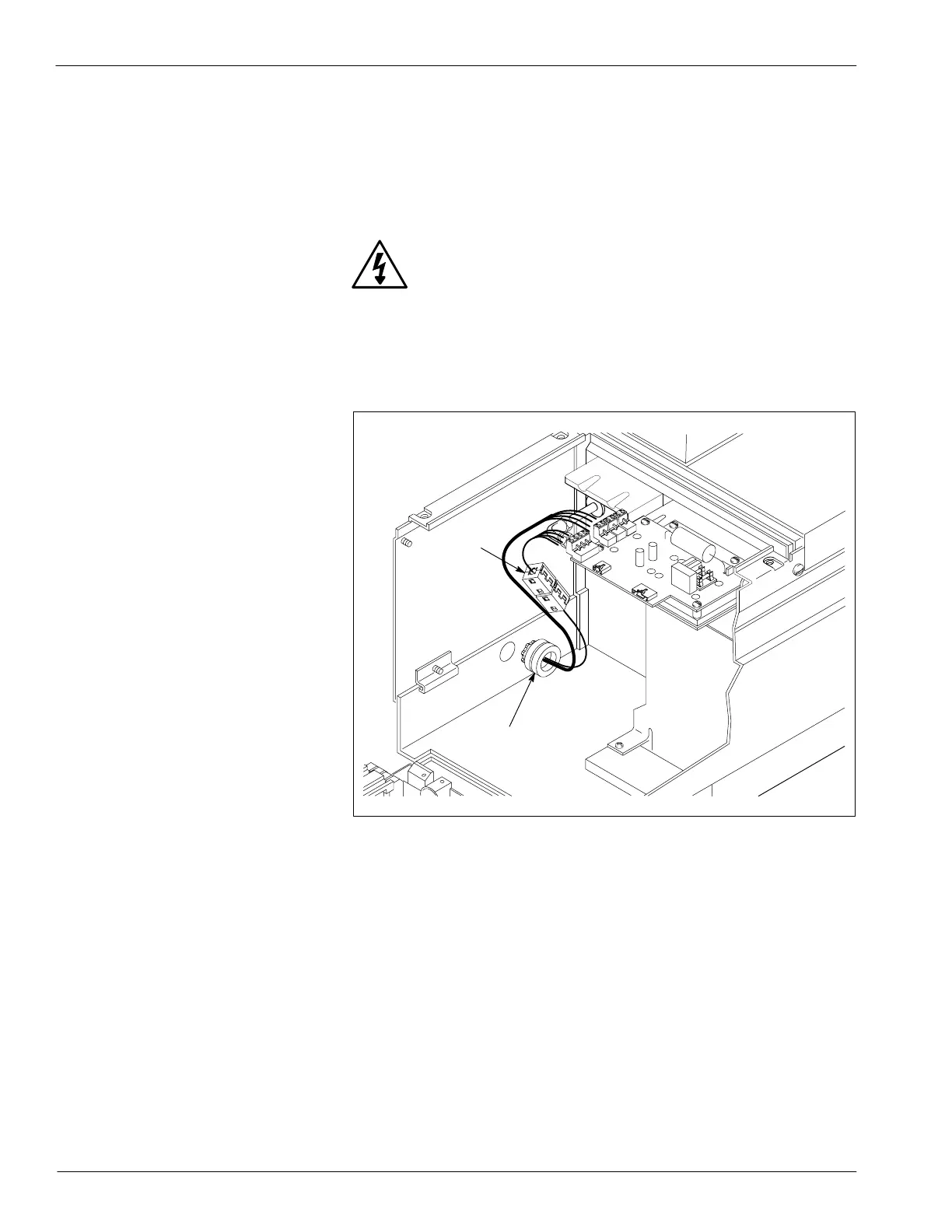
4. See Figure A 1-14. Route the input wires from your trigger devices
and your remote enable/disable device (if used) through the two
round (2) and two square (1) ferrites provided in the ship-with kit.
4130700A
1
2
Fig. A 1 -14 Installing Ferrites
1. Square ferrites 2. Round ferrites
5. Locate terminal block X6P (1) on the pattern control driver board.
Co
ec
g
e
a
ev
ce
o
he
a
e
Co
o
(contd.)
 Loading...


