LA 404 Pattern Control System
15
Part 1037527B
! 2005 Nordson Corporation
Manual 66-LA404-MA-01
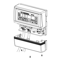
Front Panel
The front panel is used for entering and displaying the user inputs, and
transmitting the inputs to the pattern generation engine.
1
2
3
4
5
6
8
9
10
11
12
7
6640002A
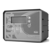
Figure 3 Location of Front Panel Controls and Indicators
Item Controls and Indicator Description
1 Right arrow or Left arrow Selects the item being programmed by moving up or down.
2 STAND BY Enables and disables the gun output. When active (amber LED) disables
all channels. When inactive (green LED) all channels are permitted to run.
3
Up (increase) arrow or
Down (decrease) arrow
Increases or decreases the value of the selected parameter.
4 OUTPUT 1–4 LEDs Illuminates when the selected gun output is activated.
5 CHANNEL SELECT Selects which channel is being programmed, observed, or adjusted.
6 ENCODER LED Illuminates with each pulse from the encoder.
7 TRIGGER LED Illuminates when the selected trigger is On.
8 CHANNEL 1–4 LEDs Illuminates to indicate that the selected channel is being programmed,
observed, or adjusted. The LEDs blink to indicate a warning condition.
9 PURGE Activates all outputs for active channel only.
NOTE: In flush mode it acts as an On/Off button. In purge mode it is a
momentary contact that is On when pressed and Off when released.
10 SET UP backward Scrolls backward through the setup screens.
11 SET UP forward Scrolls forward through the setup screens.
12
Setup menu screen Alphanumeric, 9.22 mm character height, with a 4 x 20 backlight LCD.
– Cursor or asterisk (*) Appears beside a parameter to indicate that it is ready for setup.
 Loading...