6644006A
6640004A
6640005A
F
D
G
E
C
L
A
B
K
J
H
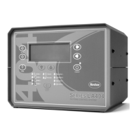
LA 404 Pattern Control System
17
Part 1037527B
! 2005 Nordson Corporation
Manual 66-LA404-MA-01
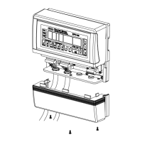
I/O Connector Pin Layout
The I/O connector pin layouts are shown below to make the appropriate
cable connections.
Runup 1 and 2
This is a female connector, the drawing shows the front view (pin side).
Pin Signal
124 VDC common
20 to 20 mA output
30 to 10 Volt output
424 VDC (0.35 A maximum)
Channel 1 – 4
This is a female connector, the drawing shows the front view (pin side).
Pin Signal
1Gun or solenoid +
2Gun or solenoid –
3 Chassis
Encoder Input
This is a female connector, the drawing shows the front view (pin side).
Pin Signal
A12 VDC (0.35 A maximum)
BSignal A (quadrature differential)
CSignal A not (quadrature differential)
DSignal B (quadrature differential)
ESignal B not (quadrature differential)
F12 VDC common
G12 VDC
HPulse train input (NPN)
J24 VDC common
KQuadrature differential encoder type (connect to
common for quadrature differential encoders)
LPulse train encoder type (connect to common for
pulse)
M12 VDC common
 Loading...