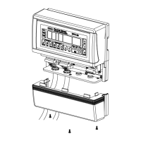
6644008A
6640006A
1
3
2
4
5
6
7
8
6640007A
F
D
G
E
C
L
A
B
K
J
H
6640005A
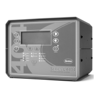
LA 404 Pattern Control System
18
Part 1037527B
! 2005 Nordson Corporation
Manual 66-LA404-MA-01
Trigger Input and Tip Seal Input
This is a female connector, the drawing shows the front view (pin side).
Pin Signal
1 N/A
2Trigger (NPN or PNP)
324 VDC (0.1 A maximum)
424 VDC common
5 N/A
Tip Seal Output
This is a female connector, the drawing shows the front view (pin side).
Pin Signal
1Tip Seal Output, 24 VDC (0.5 A maximum)
224 VDC common
3 Chassis
Remote Input
This is a female connector, the drawing shows the front view (pin side).
Pin Signal
124 VDC (0.2 A maximum)
2Remote select 0 (Remote program recall,
driven with 24 VDC)
3Remote select 1
4Remote select 2
5Remote select 3
6Remote select 4
7Remote enable
824 VDC common
Remote Output
This is a male connector, the drawing shows the rear view (solder side).
Pin Signal
ARemote output number 1, normally closed contact
BRemote output number 1, normally open contact
CRemote output number 1, common contact
DRemote output number 2, normally closed contact
ERemote output number 2, normally open contact
FRemote output number 2, common contact
Note: Pins G, H, J, L, K, and M are not used.
 Loading...