58
APPENDIX
A
Specifications Secure Router Specifications
SR1001 Installation Guide
Version 8.3.5
The following table provides information about service levels, protocols supported, and
management interface connectors.
Cable Pinouts
The following tables provide cable pinout information for the console (RJ-45), Ethernet
(RJ-45), T1(RJ-48C), and modem (DB-9 to DB-9) or (DB-25 to DB-9) cables.
Table 22 Specifications: Ethernet LAN Interface
Two 10/100 Base-T, 802.3 auto-negotiating, full or half-duplex
Table 23: Miscellaneous
Service Levels and Connectivity
DS0
NxDS0
T1
E1
NxT1
NxE1
10/100 Base-T
Protocol Support
WAN
PPP
MLPPP
HDLC
Frame Relay
Multilink Frame Relay (MFR)
FRF.15 (End-to-End)
FRF.16 (UNNI/NNI)
Management Interfaces
Console: RJ-45
AUX: DB-9
Table 24 Pinouts: Nortel-to-Terminal Console Cable (DB-9)
Nortel
DCE Pin Signal Direction
Workstation
DTE Pin
1 data carrier detect <— 1
2 transmit data —> 2
3 receive data <— 3
4 data terminal ready —> 4
5 signal ground <—> 5
6 data set ready <— 6
7 request to send —> 7
8 clear to send <— 8
9 not used 9
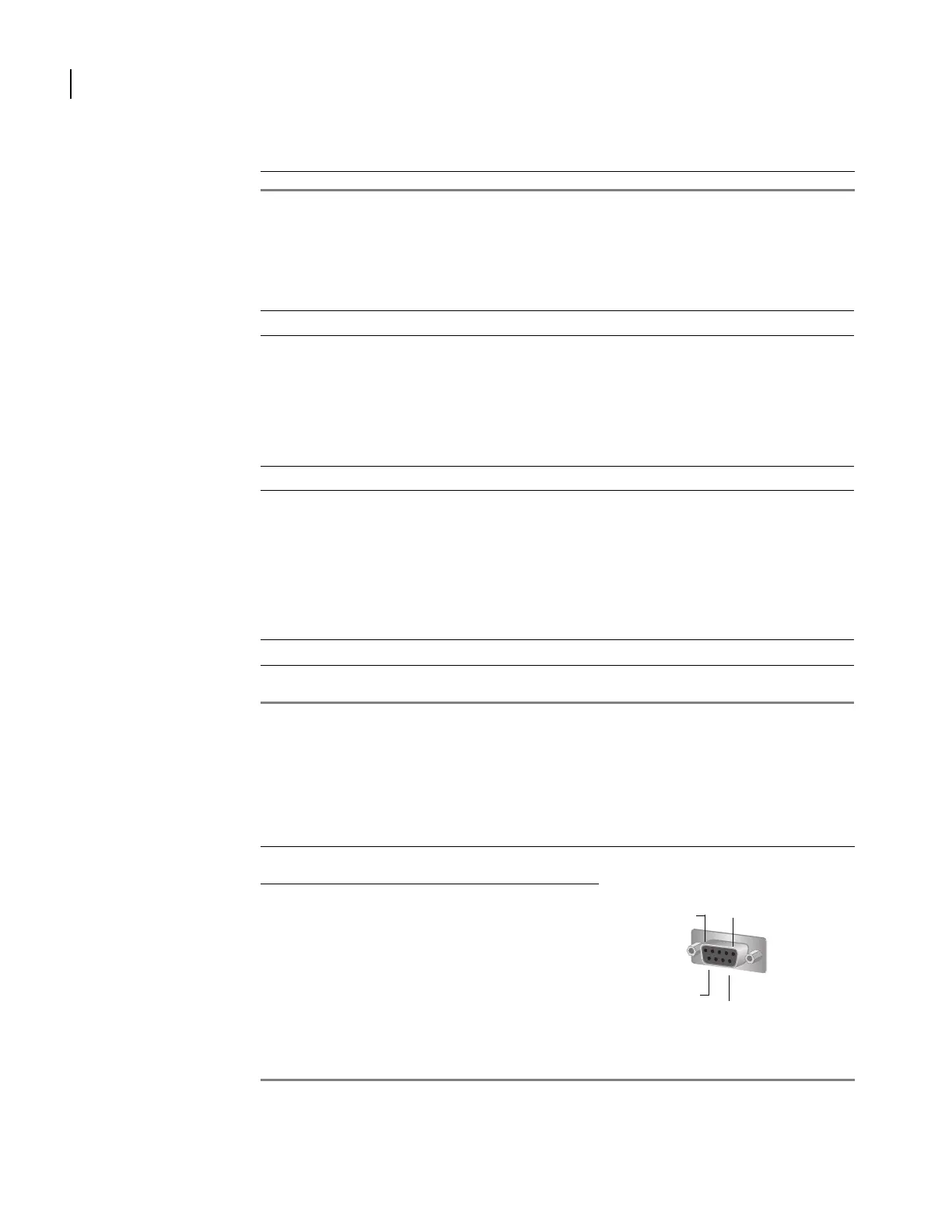
Pin 5
Pin 1
Pin 9
Pin 6
RS-232 DCE on DB-9 Female


 To Next Page