Installation, Configuration, and Programming
PN 15842:K 7/23/2002 41
4.13.3 Configuring Number of Expander Modules
Indicate the number of expanders connected to each ACM-16AT/ACM-32A by
setting the DIP switch on the end of the annunciator, as shown in Table 4-4.
Note: Switch locations are illustrated in Figure 4-4. To set a DIP switch “ON”,
push it towards the green circuit board.
Table 4-4 Configuring Number of Expanders
for ACM-16AT and ACM-32A
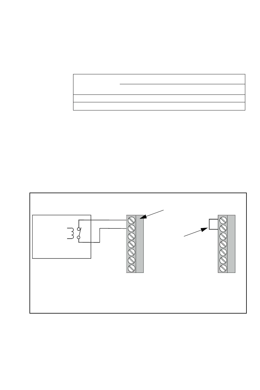
4.14 Supervising Devices with ACM-16AT, ACM-32A
If using ACM-16AT or ACM-32A, the normally closed Trouble Input on those
modules can be used for supervising local power sources or other devices. If
employed, all changes in status (to and from the trouble state) will be sent to the
control panel in the event of device failure or restoral. If not used, a jumper must
be installed across these terminals TB1-6 and TB1-7; without this jumper, the
control panel will register a trouble condition. (See Figure 4-19.)
Pin on
Annunciator DIP
Switch
Number of expanders installed
None One Two Three
2offonoffon
3offoffonon
When not using the trouble
input, jumper terminals
TB1-6 and TB1-7 together.
If an electrical short circuit
(jumper) does not exist
between terminals TB1-6 and
TB1-7, the control panel will
register a trouble condition.
Figure 4-19 Using the Trouble Input on ACM-16AT and ACM-32A
for Supervising Devices
ACSsuper.wmf
Normally
closed
trouble
contacts
5 VDC @ 0.5 mA
Trouble
Input
TB1 on
ACM-16AT,
ACM-32A
Supervised Device
TB1 on
ACM-16AT,
ACM-32A
 Loading...


