AFP-200 Systems
PN 15842:K 7/23/2002 51
APPENDIX M AFP-200 Systems
M.1 Capabilities
ACS annunciation displays the 99 software zones of the AFP-200, plus 8 system
points, for a total point count of 107. Information is transmitted using only
addresses 1 and 2. Up to 32 devices can be driven by the EIA-485
communications output, using two unique addresses with 64 points at an
address. Two-way communications can occur with only one annunciator per
address; other devices on the same address must be configured as “Receive
Only”. The furthest annunciator can be separated from the control panel by no
more than 6,000 feet of wire (@16AWG); check specific current requirements
for your system.
ACS annunciators on the AFP-200 can not be used for manual
control of control modules, bell circuits, or relays (except for global
Silence and Drill switches).
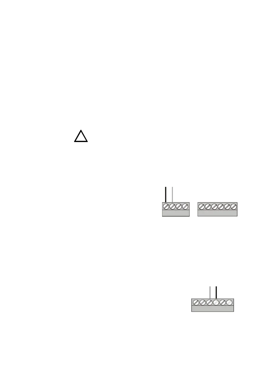
M.2 Connecting the EIA-485 Circuit
EIA-485 wiring is connected to TB5
of the AFP-200 as shown in the
accompanying illustration.
Note:
• Set SW2 on AFP-200 to “ACS”
position.
• EIA-485 circuit rated 5.5 VDC
max., 60 mA max.
See Section 3.3 “EIA-485 Wiring Specifications” for details and notes about
EIA-485 requirements.
M.3 Providing Power to Annunciators
The annunciator’s power supply is connected to
+24V non-resettable power; use the middle two pins
on TB1 of the AFP-200 as shown in the
accompanying illustration. See Section 3.6
“Annunciator Power Requirements & Electrical
Ratings” for specifications.
The power run to the annunciator need not contain a
Power Supervision Relay because loss of power is
inherently supervised through communication loss.
This 24 VDC output is power-limited, filtered, and non-resettable.
!
+ -
TB5 TB6
acs200eia.cdr
TB5 on the
AFP-200
EIA-485 output
-
+
-
+
-
+
+ -
UNRE G
+24V
NON-RST
+24V
RESET
+24V
acs200pwr.wmf
TB1 on the AFP-200
24 VDC
 Loading...


