AFP-300/AFP-400
PN 15842:K 7/23/2002 53
APPENDIX N AFP-300/AFP-400
N.1 Capabilities
When installed with an AFP-300/AFP-400, ACS annunciators can be used to
annunciate control panel status, addressable devices, panel modules, and
software zones. The fire alarm control panel uses ACS Annunciator addresses 1
through 19 (1 through 10 when employing a UDACT). Up to 32 devices can be
driven by the EIA-485 communications output, all addresses combined, with up
to 64 points to an address. Two-way communications can occur with only one
annunciator per address; other devices on the same address must be configured
as “Receive Only”.
The panel annunciation points are divided into nine groups of 64
points. Each group can be assigned to one or more of the 19
annunciator addresses supported by the AFP-300/AFP-400. See the
AFP-300/AFP-400 Programming Manual for assignment details.
N.2 Connecting the EIA-485 Circuit
EIA-485 wiring is connected to TB4 of the AFP-300/AFP-
400 as shown in the accompanying illustration.
See Section 3.3 “EIA-485 Wiring Specifications” for details
and notes about EIA-485 requirements.
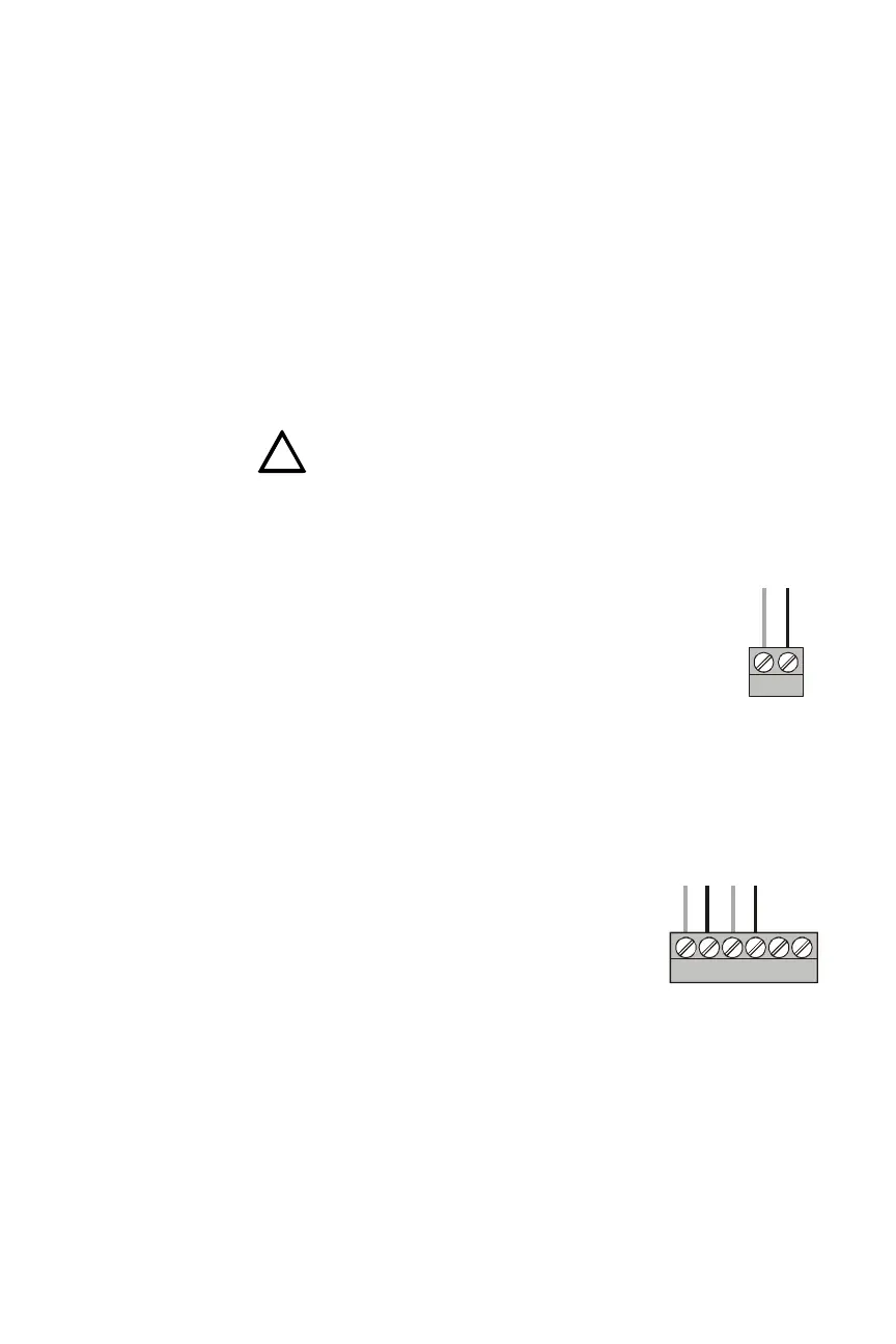
N.3 Providing Power to Annunciators
AFP-300/AFP-400 panels use Main Power Supply
MPS-400. The annunciator’s power supply is
connected to either of the MPS-400’s two non-
resettable power supplies: TB2 Terminals 1(+) and 2
(-) or TB2 Terminals 3 (+) and 4(-), as shown in the
accompanying illustration. No more than 1.25A can
be drawn from these power-limited terminals in
standby or alarm.
See Section 3.6 “Annunciator Power Requirements
& Electrical Ratings” for specifications.
The power run to the annunciator need not contain a Power Supervision Relay
because loss of power is inherently supervised through communication loss.
This 24 VDC output is power-limited, filtered, and non-resettable.
!
-
+
+ -
acs400eia.cdr
TB4 on
AFP-300/
AFP-400
+ - + -
-
+
-
+
-
+
acs400pwr.cdr
TB2 on the MPS-400
24 VDC
AB
 Loading...


