AFC-600 Systems
56 PN 15842:K 7/23/2002
APPENDIX O AFC-600 Systems
O.1 Capabilities
ACS annunciators communicate with the control panel on the ACS Mode
interface (TB4 on the AFC-600’s main circuit board). The ACS Mode interface
can annunciate control panel, zone, detector, module, and circuit status. The 832
panel annunciation points are divided into 13 fixed ACS Selection Groups
(labeled A to M) of 64 points; these are detailed in the panel's programming
guide (see Section 1.2 “Related Documentation” for part numbers). There are
also ten programmable annunciator groups which are programmed using
VeriFire™ 600 software. You can assign each ACS Selection Group to one or
more of the 32 annunciator addresses supported by the control panel.
This fire alarm control panel can use ACS annunciator addresses 1–32 without a
UDACT and ACS annunciator addresses 1–19 with a UDACT. Up to 32 devices
can be driven by the EIA-485 communications output, all addresses combined,
with up to 64 points to an address. Two-way communications can occur with
only one annunciator per address; other devices on the same address must be
configured as “Receive Only”.
Use the ACS Mode Interface to remotely use control panel functions
(Acknowledge, Alarm Silence, Alarm Activate, and System Reset) from a
remote location. The ACS Mode interface can also activate NACs, panel
circuits, and control modules from remote locations.
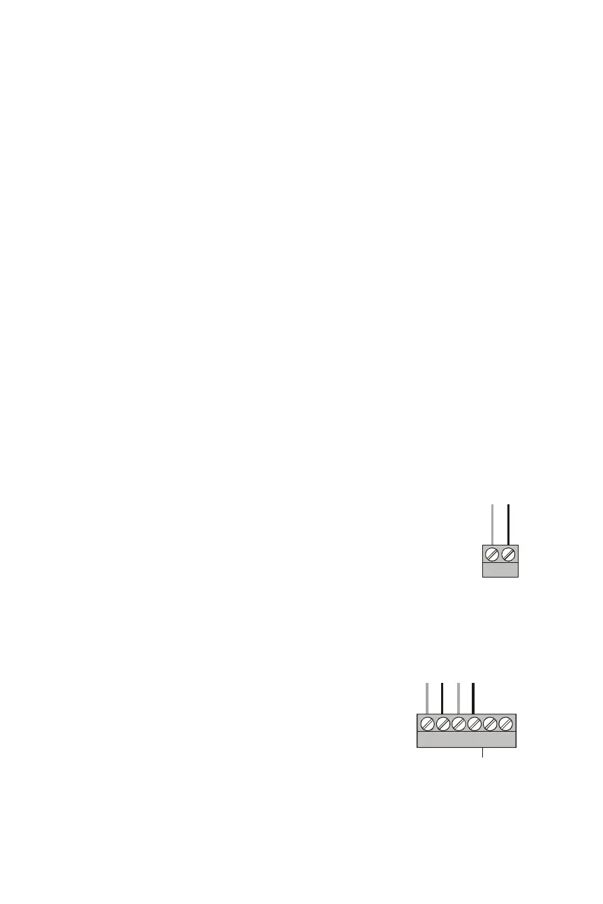
O.2 Connecting the EIA-485 Circuit
EIA-485 wiring is connected to TB4 of the AFC-600 as shown
in the accompanying illustration.
See Section 3.3 “EIA-485 Wiring Specifications” for details and
notes about EIA-485 requirements.
O.3 Providing Power to Annunciators
AFC-600 panels use Main Power Supply MPS-6.
The annunciator’s power supply is connected to
either of the MPS-6’s two non-resettable power
supplies: TB2 Terminals 1 (+) and 2(-) or TB2
Terminals 3(+) and 4(-), as shown in the
accompanying illustration. No more than 1.25A can
be drawn from these power-limited terminals in
standby or alarm.
The power run to the annunciator does not require a
Power Supervision Relay. Loss of power is
inherently supervised through a Communications loss. This 24 VDC output is
supervised, power-limited, filtered, and non-resettable.
-
+
+ -
acs400eia.cdr
TB4 on
AFC-600
+ -+ -
-
+
-
+
-
+
NONRESET 24V PWR LTD RESET
acsmps6pwr.cdr
TB2 on the MPS-6
24 VDC
 Loading...


