Installation, Configuration, and Programming
PN 15842:K 7/23/2002 29
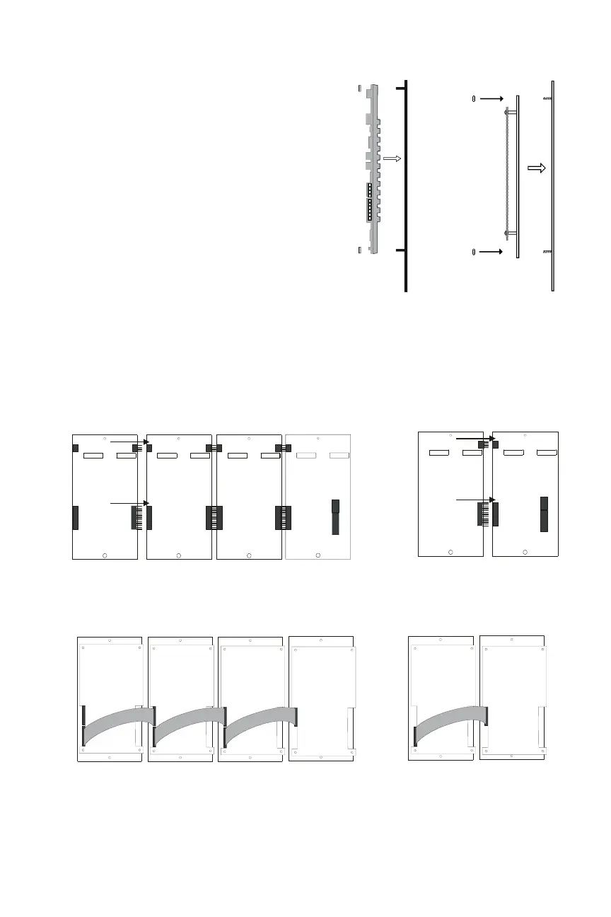
Plug the two annunciator
terminal blocks into the
annunciator to complete
communication and power
circuit connections as
described in Section 4.5
and Section 4.9.
If using an annunciator
backbox, place the
annunciator/dress-plate
assembly into the backbox
and secure with two
screws.
If using a semi-flush-
mount backbox, attach
door. Align the door with
the dress plate, and slide
the door down onto the
pins on the dress plate.
When positioned correctly, the door will open and close freely (see diagram in
Section 2.5 “Cabinet & Panel Hardware”).
Figure 4-6 Mounting to the Dress Plate
ACM-16AT, ACM-32A,
and Expanders
ACM-24AT, ACM-48A,
and Expanders
Figure 4-7 Connecting ACM-24AT and AEM-48A to Expander Modules
TB2 PWR SUPPLY
+24VREFRS4 85 +RS48 5-REFEGND
RS485 INTFC
TB1
J2J1
J3
J1
J4 J3
J1
J3
J4
J2 J1
J3 J4
J2
acm24at-aem.cdr
ACM-24ATAEM-24ATAEM-24ATAEM-24AT
J2
J4
J1
J3
J2
TB2 PWR SUPPLY
+24VREF
RS485+RS485-
REFEGND
RS485 INTFC
TB1
acm48-aem.cdr
ACM-48AAEM-48A
J2J2
P3
J2
P3
J2
P3
J2
P3
ACM16AT-AEM.cdr
Figure 4-8 Connecting ACM-16AT and ACM-32A to Expander Modules
ACM32A-AEM.cdr
ACM-16ATAEM-16ATAEM-16ATAEM-16AT
ACM-32AAEM-32A
 Loading...


