Installation, Configuration, and Programming
30 PN 15842:K 7/23/2002
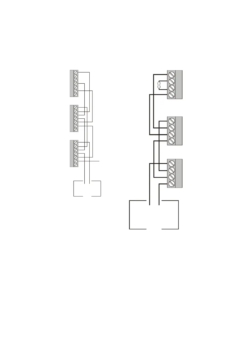
4.5 EIA-485 Circuit Connections
The accompanying figures provide EIA-485 circuit diagrams for the two
different types of annunciators.
Note: See Section 3.3 “EIA-485 Wiring Specifications” for circuit
requirements.
-
-
+
+
EIA-485
-
-
+
+
-
-
+
+
3
4
1
2
7
5
6
3
4
1
2
7
5
6
3
4
1
2
7
5
6
-
+
ACM-24-48-eia.cdr
REF
+ IN
+ OUT
- OUT
- IN
Ref Out
Ref In
EGnd
+ IN
+ OUT
- OUT
- IN
Ref Out
Ref In
EGnd
+ IN
+ OUT
- OUT
- IN
Ref Out
Ref In
EGnd
Note: See Section 4.7 “End of Line
Resistor for EIA-485 Circuit” to set on-
board ELR for ACM-24AT/ACM-48A.
Figure 4-9 EIA-485 Circuit for
ACM-24AT and ACM-48A
-
-
+
+
-
-
+
+
-
-
+
+
-
+
Figure 4-10 EIA-485 Circuit
for ACM-16AT and ACM-32A
TB2 on Last
Annunciator
EIA-485 Circuit from
Control Panel
acs_eia.cdr
In
Out
Out
In
TB2 on First
Annunciator
TB2 on Middle
Annunciators
In
Out
Out
In
In
Out
Out
In
 Loading...


