AFP-3030 Installation Manual — P/N DOC-01-037:B 25/08/2016 28
Wiring a Signalling Line Circuit (SLC) Installation
2. Loops must be programmed for Rapid Poll (refer to the programming manual for specific
instructions).
3. Modules on a fully loaded loop must adhere to a ratio of two monitor modules to one control
module.
3.12.3 SLC Installation
Install loop control and expander modules as described in Section 3.5 “Connecting the Loop
Control and Expander Modules”. Note that the unique SLC loop number assigned to a module does
not need to match the module’s location in the cabinet. For details on designing, installing and
configuring SLC loops, see the SLC Wiring Manual.
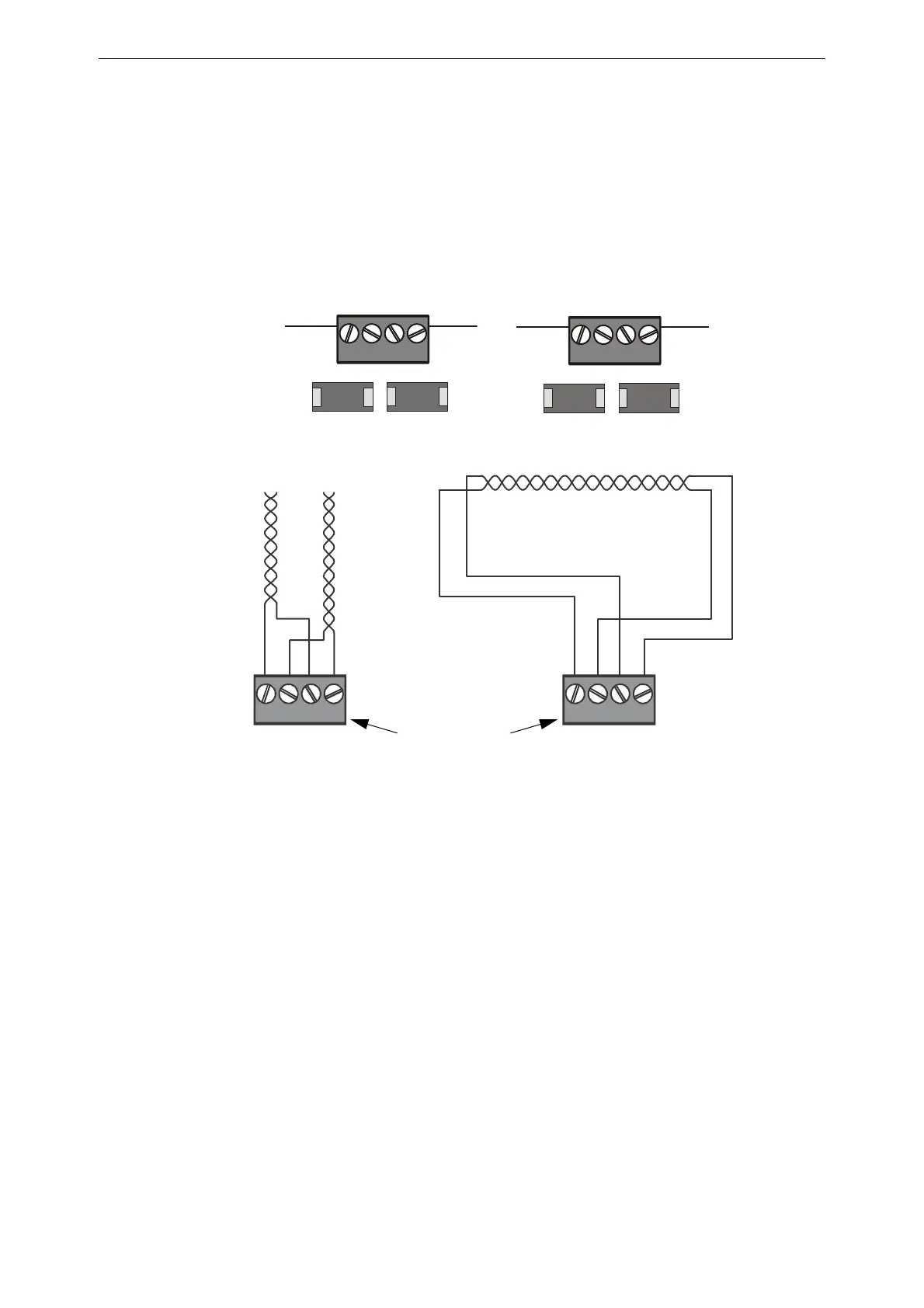
B+ A+ B- A- B+ A+ B- A-
T-Tapping is not allowed
on a four-wire SLC.
Channel B (output loop)
Channel A (loop return)
Open Wiring (Style 4)
SLC Loops
Closed Wiring (Style 6/7)
SLC Loops
SLC Loop #2 Connections
on Loop Expander Module
SLC Loop Connections
on Loop Control Modules
SLC loop
connections are
the same for Loop
Expander and
Control Modules
Channel
B
Channel
A
3030-slcloops.cdr
Figure 3.21 SLC Loop Connections and Wiring
 Loading...


