AFP-3030 Installation Manual — P/N DOC-01-037:B 25/08/2016 14
Connecting the Network Communications Module Installation
3.4 Connecting the Network Communications Module
If networking two or more control panels (or network control annunciators), each one requires a
Network Communications Module; a wire version and a fibre version are available. The wire and
fibre versions on the NCM or HS-NCM can be installed on the CPU and power supply assembly.
The preferred position is on top of the CPU assembly, as shown in Figure 3.3.
1. Mount the NCM or HS-NCM in the selected position. (See Figure 3.3)
2. Connect J1 on the CPU to J3 on the NCM or J6 on the HS-NCM using the network cable
provided (P/N 75556). Do not connect two NCMs via NUP ports (aka NUP to NUP).
3. When installing an NCM: Connect Channel A and/or Channel B as described in the NCM
Installation Document.
When installing a HS-NCM: Connect Channel A to Channel B as described in the HS-NCM
Installation Document.
3.5 Connecting the Loop Control and Expander Modules
3.5.1 Mounting Instructions
Mount loop control and expander modules within the cabinet with the CPU. Typical mounting
positions are in the row immediately below the fire panel. Follow the basic chassis-mounting
instructions given for option boards. Loop-expander modules are mounted first; Loop-control
modules are mounted on top of those. Alternately, loop-control and loop-expander modules can be
attached to each other and mounted as a pair to the chassis. See Figure 3.5 for connection
instructions, connector locations and stand-off lengths.
If using loop control and expander modules in CHS-4L see Figure 3.6.
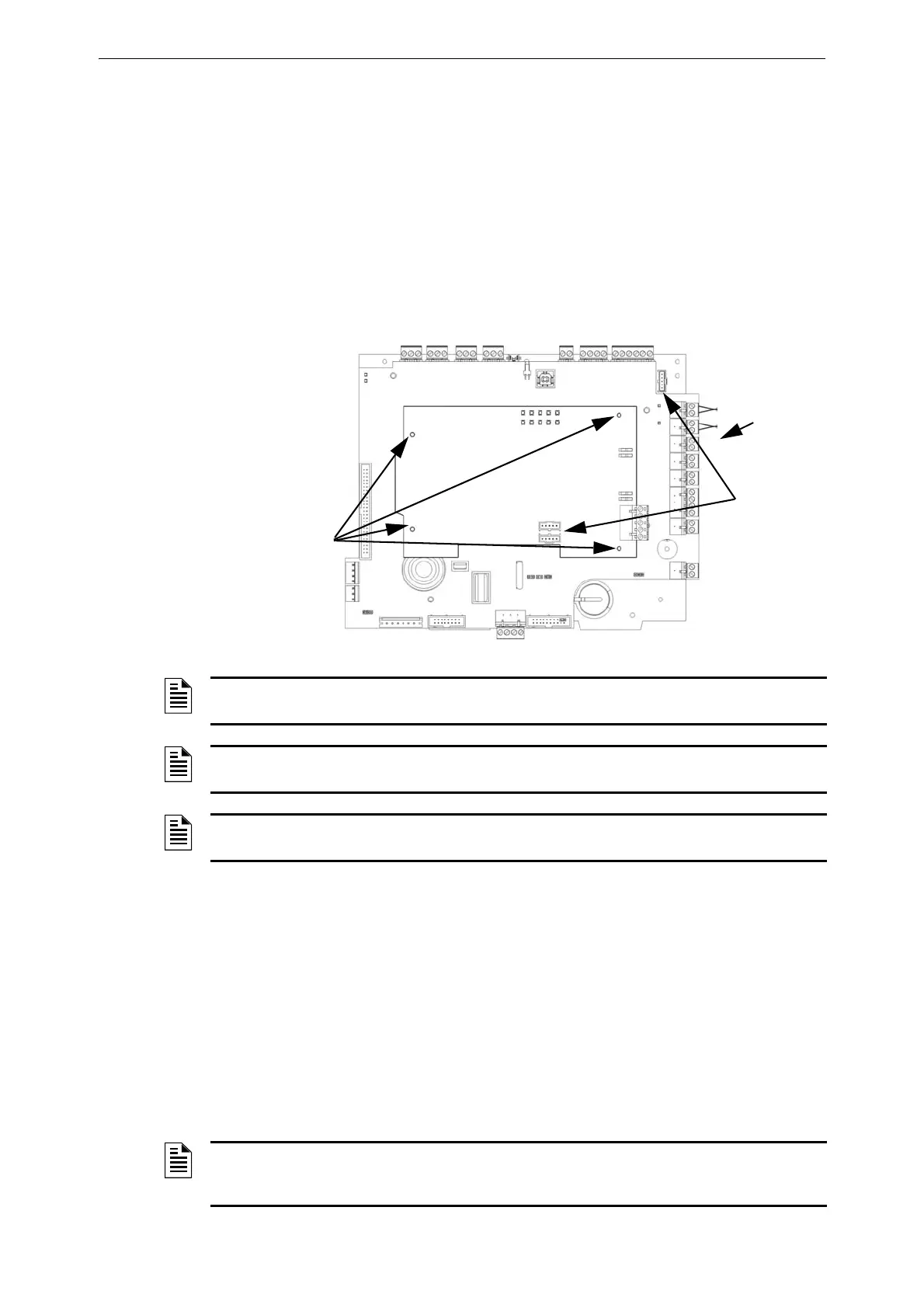
Figure 3.3 Mounting an NCM/HS-NCM to the CPU Assembly
psi-network-card.jpg
CPU
Assembly
NCM or
HS-NCM
Fasten the
NCM/HS-NCM to
the CPU Assembly
using the screws
and standoffs
included with your
network card.
NUP Port
connections:
Connect NUP
cable from
NCM/HS-
NCM to J1 on
the fire panel
NOTE: See the Noti•Fire•Net Version 5.0 & Higher Manual and the NCM Installation Document
or the High-Speed Noti•Fire•Net Manual for system configuration information.
NOTE: Over-bending fibre-optic cable can damage it. Do not exceed a 8 cm minimum bend
radius.
NOTE: NCM hardware is not compatible with HS-NCM hardware and should not be mixed on
the same network.
NOTE: Mounting two pairs of loop control and expander modules in one chassis position may
cause intermittent electrical interference. If this occurs, move one pair to a separate chassis
position.
 Loading...


