AFP-3030 Installation Manual — P/N DOC-01-037:B 25/08/2016 16
Connecting the Loop Control and Expander Modules Installation
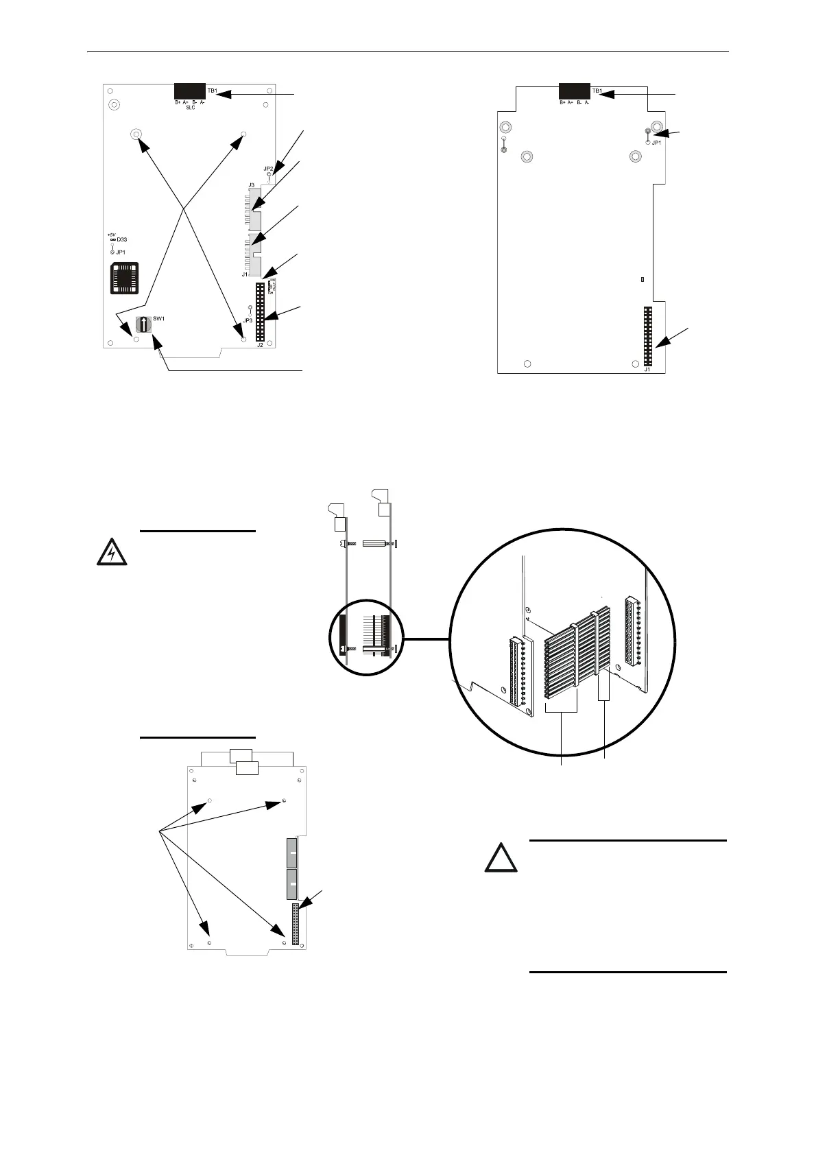
SW1 Set to assign a unique
SLC loop number
J3 Data Out to
next LCM-320
J1 Data In from control panel
or from previous LCM-320
Ground Fault LEDs:
D32 Loop Expander
Module Ground Fault
D28 Loop Control Module
Ground Fault
J2 LEM-320 Connection
TB1 SLC
Loop
Connection
LCM-320
Connection
LCM-320 LEM-320
Note: Do not cut any jumpers on the LCM-320 or LEM-320.
TB1 SLC Loop
Connection
LCM-320.wmf
LEM-320.wmf
Figure 3.4 LCM-320 and LEM-320 Diagram
JP2 See note.
Stand-off
locations
JP1 See note.
Figure 3.5 Connecting Loop Control Modules with Loop Expander Modules
Loop
Expander
Module
Loop
Control
Module
J1
J2
Loop
Expander
Module
Loop
Control
Module
The long-pin end plugs
directly into the back of
the Loop Control
Module board.
The short-pin end
plugs directly into
the top of the
Loop Expander
Module plug.
Stand-off
locations
J2 on LCM-320
“LEM-320 Data”
Loop Expander Module mounted
behind Loop Control Module
LEM-LCM.cdr
CAUTION:
IF THE STACKER-CONNECTOR
IS INSTALLED UPSIDE-DOWN,
THE SHORT-PIN END OF THE
PLUG CAN FAIL TO MAKE A
SECURE CONNECTION WHEN
PLUGGED THROUGH THE LOOP
CONTROL MODULE.
WARNING: RISK
EQUIPMENT
DAMAGE.
USE SPECIFIED
STAND-OFF
MOUNTING
LOCATIONS ONLY.
SEE FIGURES 3.4
AND 3.5. DO NOT
USE CORNER
HOLES FOR
INSTALLATION
PURPOSES.
 Loading...


