17 AFP-3030 Installation Manual — P/N DOC-01-037:B 25/08/2016
Installation Connecting the Loop Control and Expander Modules
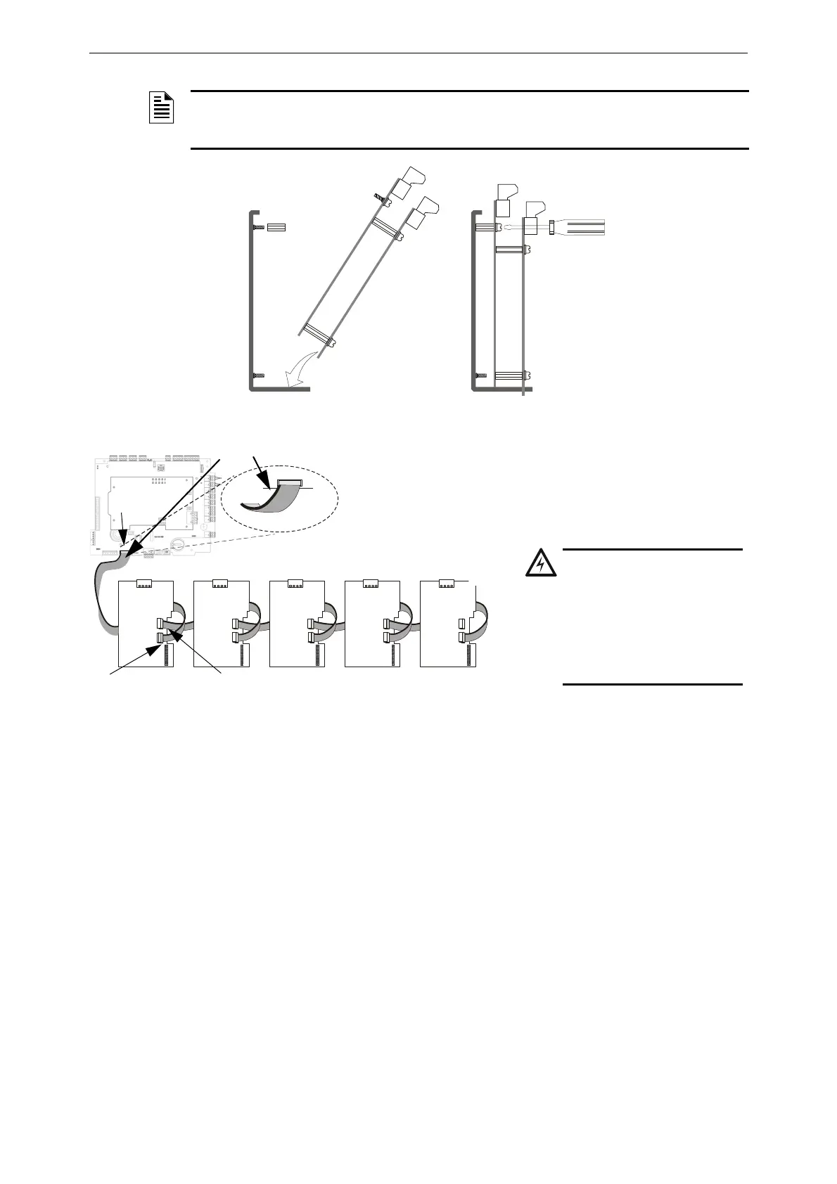
NOTE: Depending on system components, clearance may be tight. Do not force modules! Move
the assembly around gently until you find the angle where components and mounting studs pass
each other without scraping together.
Angle tab on loop control module
into slot on CHS-4L
Use a slimline screwdriver (3/32”) to
fasten down LEM-320 through the
hole in the LCM-320 board.
CHS-4L-LEM-LCM.cdr
Figure 3.6 Inserting Pair of Loop Control and Expander Modules into CHS-4L
For mounting
in CHS-3L,
see Figure 3.1
Figure 3.7 Connecting Multiple Pairs of Loop Control and Expander Modules
J22 on PSU
J1 on LCM-320
“Data in”
J3 on LCM-320
“Data out”
3030LCMchainrv2.wmf
Figure 3.7 Connecting Multiple Pairs of Loop Control and Expander Modules
NOTE:
The red stripe on the ribbon cable indicates position 1. Position 1 of
the ribbon cable should line up with position 1 on J7 of the CPU
and J1 and J3 of the LCM-320.
WARNING: INSTALL THE
RIBBON CABLE AS SHOWN.
DO NOT FORCE OR MODIFY
THE CABLE TO FIT ANY
OTHER WAY. EQUIPMENT
DAMAGE CAN RESULT
FROM INCORRECT
ALIGNMENT.
The red stripe on the ribbon cable
is indicated by the dark line
 Loading...


