25 AFP-3030 Installation Manual — P/N DOC-01-037:B 25/08/2016
Installation Installing Printers
Table 3.2 contains a checklist for checking the system with AC power applied to the main power
supply:
3.10.4 Auxiliary Power Supply Connections
If an optional auxiliary power supply is installed in the cabinet, connect it at this time. Follow the
connection procedures specified by your auxiliary power supply.
3.11 Installing Printers
This section contains information on connecting a printer to the CPU and for setting the printer
options. The basic steps are as follows:
1. Make custom cable & connect it from printer to EIA-232 terminal on the CPU.
2. Connect printer’s power supply.
3. Configure printer settings as described in printer documentation.
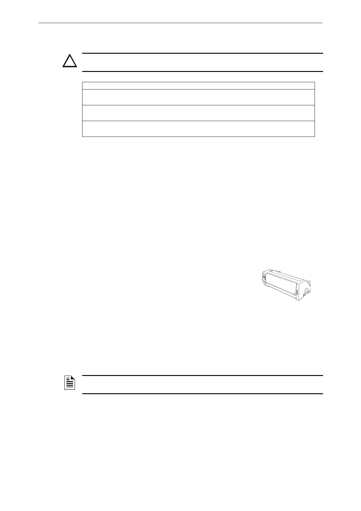
Overview: PRN Printer
The PRN provides a printed record (80 columns on standard 9" x 11"
tractor-feed paper) of all system events (alarm, trouble) and status
changes within the system. The control panel can be configured to
time-stamp the printout with the current time-of-day and date for each
event. The printer can be located up to 15 metres from the control
panel. Installation and configuration instructions follow.
3.11.1 Printer Installation Sequence
1. Fabricate a custom cable to connect a printer to the system. Length of the cable will vary with
each installation, but should not exceed a maximum length of 15 metres. Printer must be
installed in the same room as panel. Using overall foil/braided-shield twisted-pair cable,
properly connect one end to the DB-25 Connector (provided) using the wiring specifications
shown in Figure 3.20.
2. Tighten clamp on connector to secure cable. Connect the four open leads of the custom cable to
the TB5 terminal block on the CPU as shown in Figure 3.20.
CAUTION:
WHILE CHECKING AC POWER, MAKE SURE BATTERIES ARE NOT CONNECTED.
Component Status
CPU/PSU The green Operating indicator will come on when power is
coming from the main power supply.
Main power
supply
The green Operating indicator will come on when AC is supplied.
Each auxiliary
power supply
Refer to the panel’s LCD display for any auxiliary power supply
issues.
Table 3.2 AC Power Checklist
NOTE: Alternative wiring specifications are also shown in Figure 3.20 for a printer with a 9-pin
connector. Refer to printer manual for detailed connection information.
 Loading...


