ANALOG SYSTEM LINES TEST PROCEDURE
q Before powering the control panel lines, verify the following values:
»
NOTE : DIGITAL VOLTAGE METER NEEDED
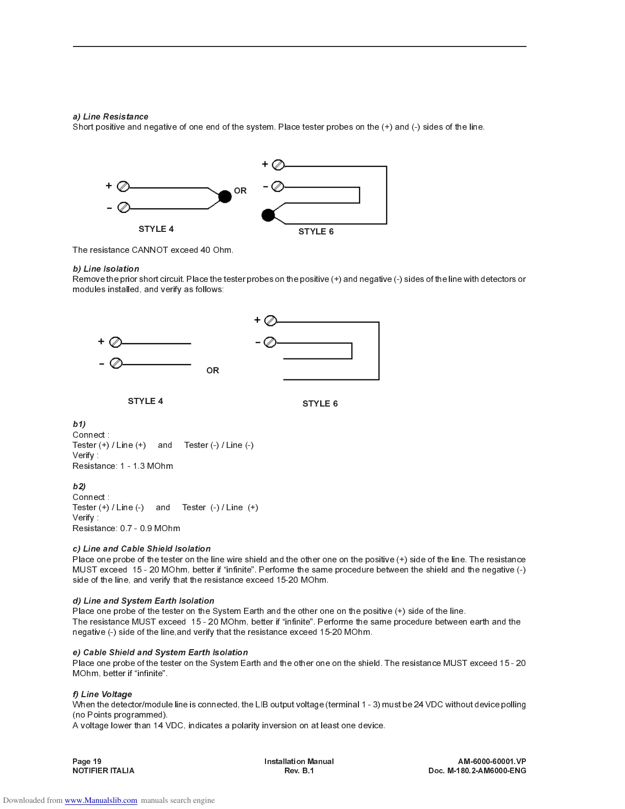
a) Line Resistance
Short positive and negative of one end of the system. Place tester probes on the (+) and (-) sides of the line.
The resistance CANNOT exceed 40 Ohm.
b) Line Isolation
Remove the prior short circuit. Place the tester probes on the positive (+) and negative (-) sides of the line with detectors or
modules installed, and verify as follows:
b1)
Connect :
Tester (+) / Line (+) and Tester (-) / Line (-)
Verify :
Resistance: 1 - 1.3 MOhm
b2)
Connect :
Tester (+) / Line (-) and Tester (-) / Line (+)
Verify :
Resistance: 0.7 - 0.9 MOhm
c) Line and Cable Shield Isolation
Place one probe of the tester on the line wire shield and the other one on the positive (+) side of the line. The resistance
MUST exceed 15 - 20 MOhm, better if infinite. Performe the same procedure between the shield and the negative (-)
side of the line, and verify that the resistance exceed 15-20 MOhm.
d) Line and System Earth Isolation
Place one probe of the tester on the System Earth and the other one on the positive (+) side of the line.
The resistance MUST exceed 15 - 20 MOhm, better if infinite. Performe the same procedure between earth and the
negative (-) side of the line,and verify that the resistance exceed 15-20 MOhm.
e) Cable Shield and System Earth Isolation
Place one probe of the tester on the System Earth and the other one on the shield. The resistance MUST exceed 15 - 20
MOhm, better if infinite.
f) Line Voltage
When the detector/module line is connected, the LIB output voltage (terminal1-3)must be 24 VDC without device polling
(no Points programmed).
A voltage lower than 14 VDC, indicates a polarity inversion on at least one device.
Page 19 Installation Manual AM-6000-60001.VP
NOTIFIER ITALIA Rev. B.1 Doc. M-180.2-AM6000-ENG
STYLE 6
OR
STYLE 4
OR
STYLE 4
STYLE 6