MAIN POWER SUPPLY CURRENT DRAW CALCULATION
The Main Power Supply must be capable of powering, all internal system devices (and all external devices)
continuously during stand-by condition, which means non-fire alarm condition.
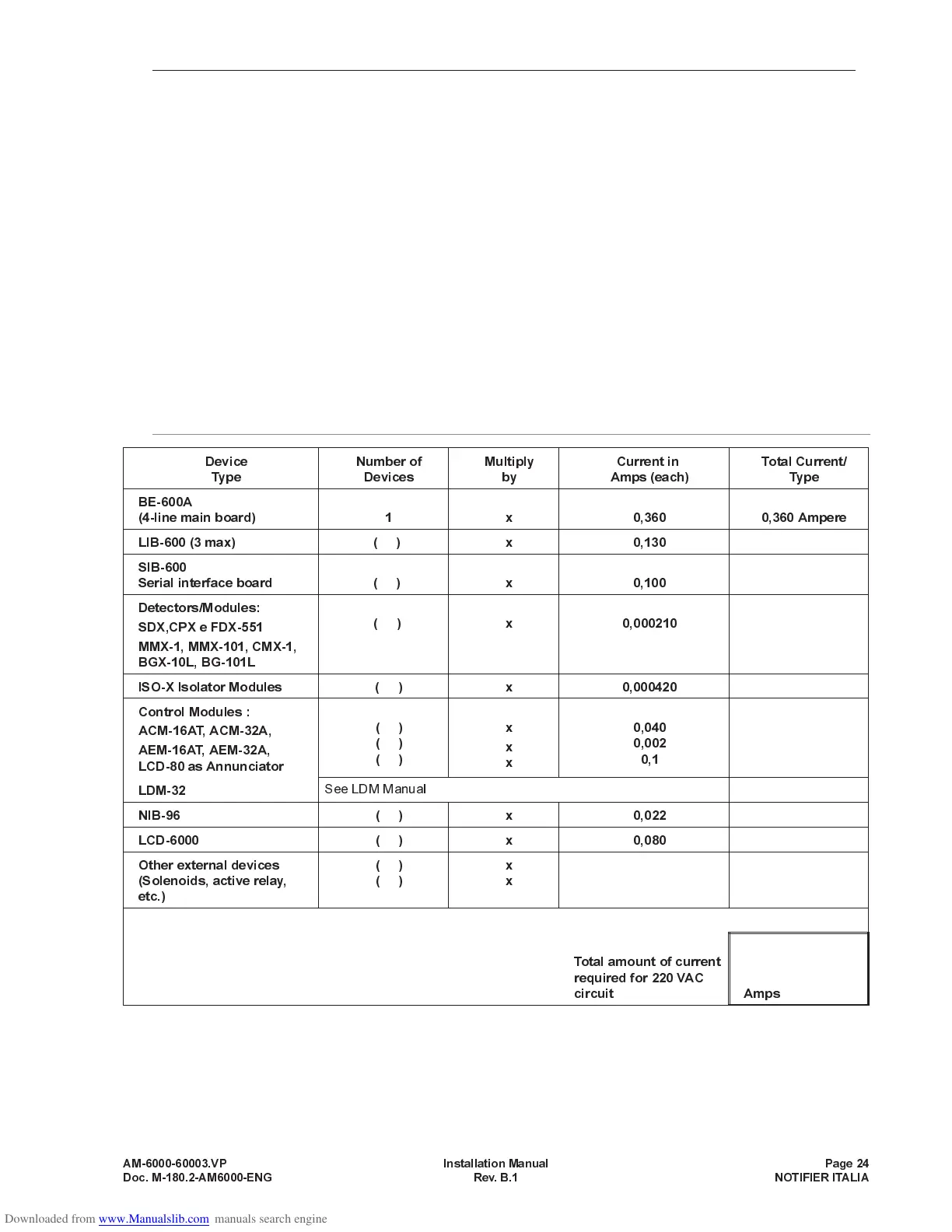
Use table 2 to determine the stand-by load.
Use table 3 to determine the additional current needed during Alarm condition.
The requirements for stand-by and alarm current loads cannot exceed the capabilities of the power supply in
either case.
The Main Power supply provides a 24 VDC current up to 3.0 amps so that the system could operate during
stand-by or alarm condition.
The current load values into tables 2 and 3 are also valid for the AVPS-6 auxiliary power supply.
Fill in the table 2 for devices that must be steadly powered only.
»
NOTE
for conventional detectors : in table 2 use the current value indicated for the stand-by condition
(refer to manufacturer’s instructions for detector current draws).
Write the alarm condition absorptions into table 3.
TABLE 2: stand-by condition current requirements (24 VDC)
»
NOTE: the total of stand-by load obtained in table 2 CANNOT exceed the following values:
- 3.0 Amps for Main Power Supply
- 3.0 Amps for Auxiliary Power Supply (AVPS-6)
AM-6000-60003.VP Installation Manual Page 24
Doc. M-180.2-AM6000-ENG Rev. B.1 NOTIFIER ITALIA
Device
Type
Number of
Devices
Multiply
by
Current in
Amps (each)
Total Current/
Type
BE-600A
(4-line main board) 1 x 0,360 0,360 Ampere
LIB-600 (3 max) ( ) x 0,130
SIB-600
Serial interface board ( ) x 0,100
Detectors/Modules:
SDX,CPX e FDX-551
MMX-1, MMX-101, CMX-1,
BGX-10L, BG-101L
( ) x 0,000210
ISO-X Isolator Modules ( ) x 0,000420
Control Modules :
ACM-16AT, ACM-32A,
AEM-16AT, AEM-32A,
LCD-80 as Annunciator
()
()
()
x
x
x
0,040
0,002
0,1
LDM-32
See LDM Manual
NIB-96 ( ) x 0,022
LCD-6000 ( ) x 0,080
Other external devices
(Solenoids, active relay,
etc.)
()
()
x
x
Total amount of current
required for 220 VAC
circuit Amps