CONNECTOR CN1 on “BE-600 A” BOARD
»
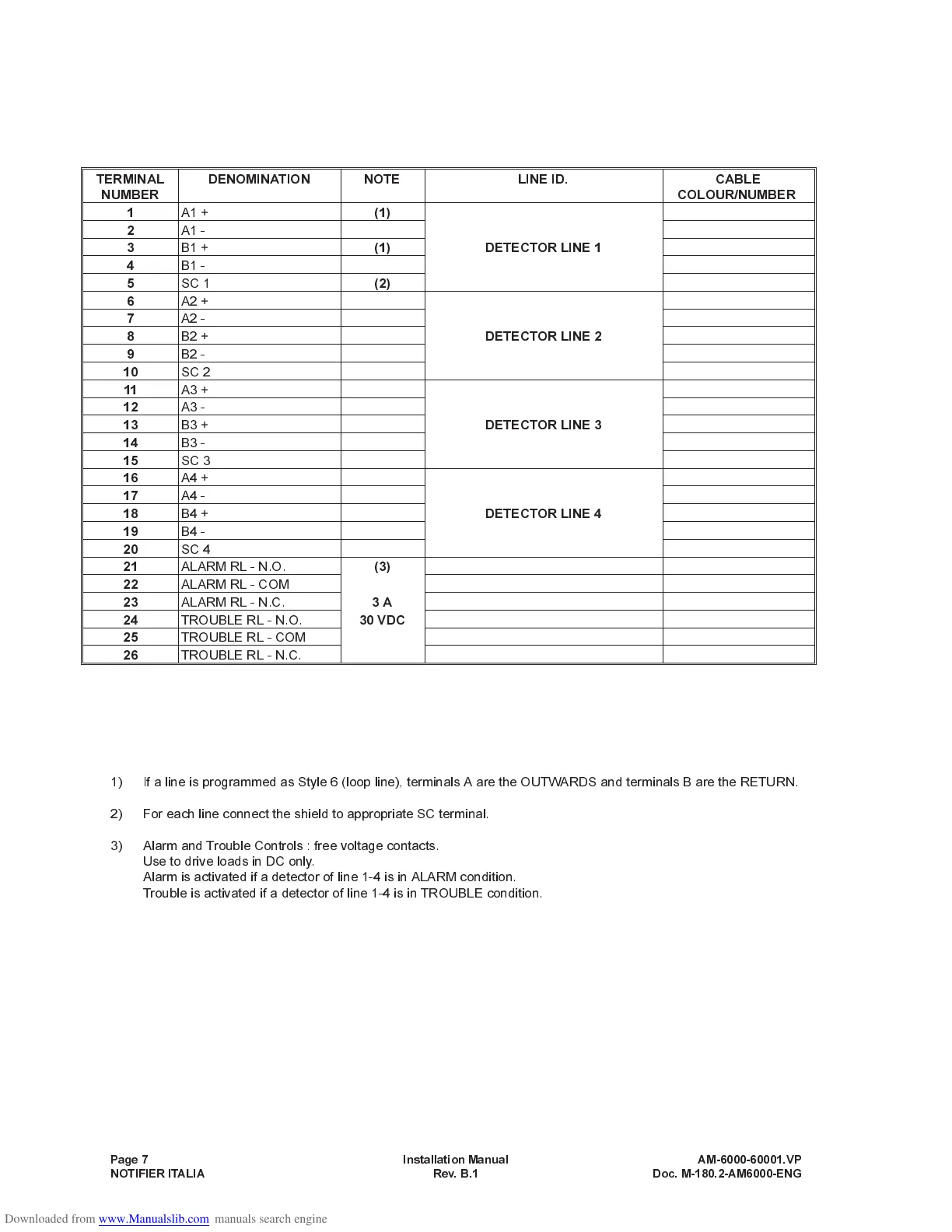
NOTE :
1) If a line is programmed as Style 6 (loop line), terminals A are the OUTWARDS and terminals B are the RETURN.
2) For each line connect the shield to appropriate SC terminal.
3) Alarm and Trouble Controls : free voltage contacts.
Use to drive loads in DC only.
Alarm is activated if a detector of line 1-4 is in ALARM condition.
Trouble is activated if a detector of line 1-4 is in TROUBLE condition.
Page 7 Installation Manual AM-6000-60001.VP
NOTIFIER ITALIA Rev. B.1 Doc. M-180.2-AM6000-ENG
TERMINAL
NUMBER
DENOMINATION NOTE LINE ID. CABLE
COLOUR/NUMBER
1
A1 +
(1)
2
A1 -
3
B1 +
(1) DETECTOR LINE 1
4
B1 -
5
SC 1
(2)
6
A2 +
7
A2 -
8
B2 +
DETECTOR LINE 2
9
B2 -
10
SC 2
11
A3 +
12
A3 -
13
B3 +
DETECTOR LINE 3
14
B3 -
15
SC 3
16
A4 +
17
A4 -
18
B4 +
DETECTOR LINE 4
19
B4 -
20
SC 4
21
ALARM RL - N.O.
(3)
22
ALARM RL - COM
23
ALARM RL - N.C.
3A
24
TROUBLE RL - N.O.
30 VDC
25
TROUBLE RL - COM
26
TROUBLE RL - N.C.