Section 2 Installation
14 PN 50702:B2 4/14/03
.
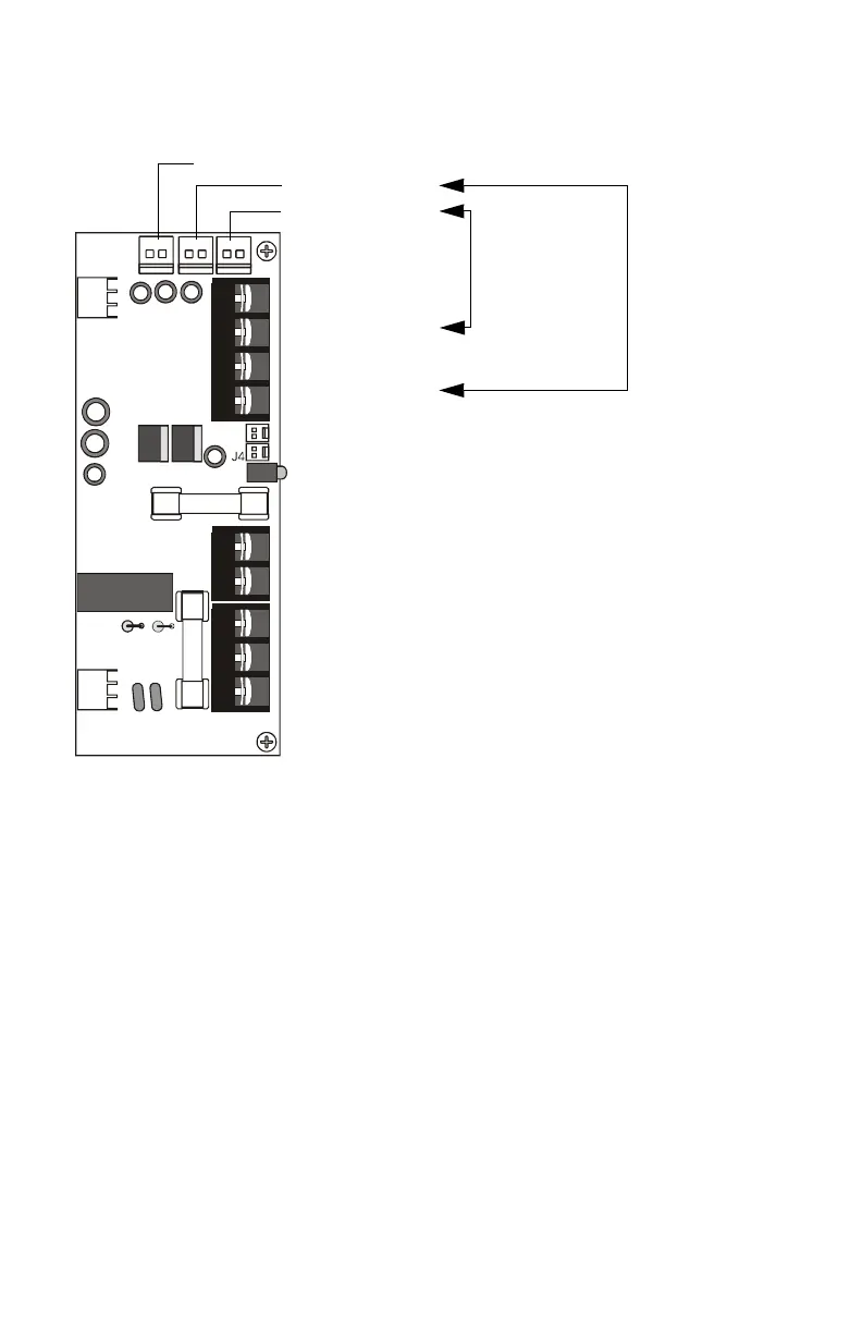
Figure 5 Typical Wiring for an APS-6R
J2
J9
J3
J1
TB2
TB3
TB1
JP3
JP2
TB2:
Output Circuit 1
TB1 - Primary Power:
120 VAC or 240 VAC.
TB3 - Secondary Power: 24 VDC batteries.
Trouble Bus In/Out
TB2:
Output Circuit 2
Earth Ground - Connects to chassis or
EARTH
ground terminal on main power supply. If 2 or
more units are connected, secondary units
connect to earth ground on the previous
APS-6R in the chain.
-
s
e
r
.c
r
BATT (+)
BATT (–)
HOT
NEUTRAL
EARTH
J9:Output Circuit 3 - Non Power-limited, 6 A @24 VDC (+10, –15%)
+
–
+
–
- +
J1:Output Circuit 1
J2:Output Circuit 2
- + - +
(
Refer to the caution above this illustration
about secondary power and supervision)
Output Circuit 2
(J2 and TB2):
Power-limited
3 A @24 VDC
(+10, –15%)
Output Circuit 1
(J1 and TB2):
Power-limited
3 A @24 VDC
(+10, –15%)
See Page 18 in
"Configuring the
APS-6R".
www.PDF-Zoo.com