Section 2 Installation
PN 50702:B2 4/14/03 19
Servicing the APS-6R
The only serviceable components on the APS-6R are fuses F1 and F2.
If a fuse fails, replace it with a fuse of the same type and rating:
• F1 AC protection - 4A, 3 AG
• F2 Battery protection - 10A, 3 AG
To replace either fuse remove the vertical APS-6R control board as
follows:
1. Turn off and remove all power sources.
2. Remove plastic cover.
3. Remove the two retaining screws securing control board.
4. Unplug the control PC board from the connectors.
5. Replace fuses as required.
6. Reinstall board in reverse order, install plastic cover and connect all
power.
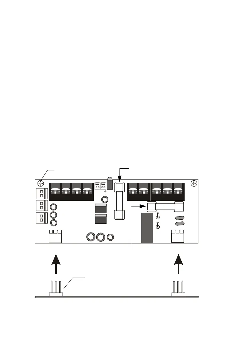
The figure below illustrates the location of the fuses.
Figure 10 Servicing the APS-6R
J2
J9
J3
J1
TB2
JP3
JP2
F2 Fuse
Retaining Screw (typ)
F1 Fuse
Connector (typ)
APS-6Rservice.cdr
Main Circuit Board
www.PDF-Zoo.com