APPENDIX G - NFS-3030
28 PN 50702:B2 4/14/03
APPENDIX G - NFS-3030
Mounting an APS-6R in a Chassis
An Auxiliary Power Supply is mounted on a CHS-4 Series chassis.
See “Mounting in CAB-3/CAB-4 Series Cabinets” on page 12..
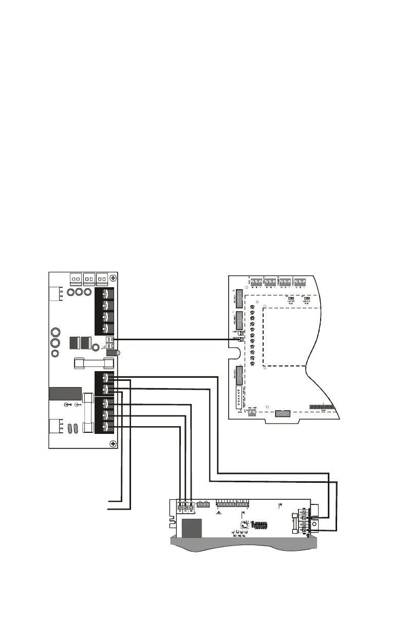
Connecting to the AMPS-24 and CPU-3030
Make the following connections as shown in the figure below.
• Connect primary power from TB1 on the APS-6R to TB3 HOT,
NEUT and EARTH on the AMPS-24.
• Connect secondary power from TB3 BATT(+) and BATT(-)on
the APS-6R to TB5 (BAT IN +) and TB4 (BAT OUT-)
respectively on the AMPS-24.
• Connect trouble input from J3 on the APS-6R to the J5 Trouble
bus connection on the CPU-3030.
Figure 19 Wiring to AMPS-24 and CPU-3030
J2
J9
J3
J1
TB2
TB3
TB1
JP3JP2
To battery
backup
+
-
AMPS-24
CPU-3030
APS-6R to NFS-3030.cdr
www.PDF-Zoo.com