Section 2 Installation
16 PN 50702:B2 4/14/03
Wiring Applications
This section contains instructions for wiring the APS-6R assembly as
follows:
• Connecting the APS-6R to an ICM/ICE module
• Supplying notification appliance power to a control module
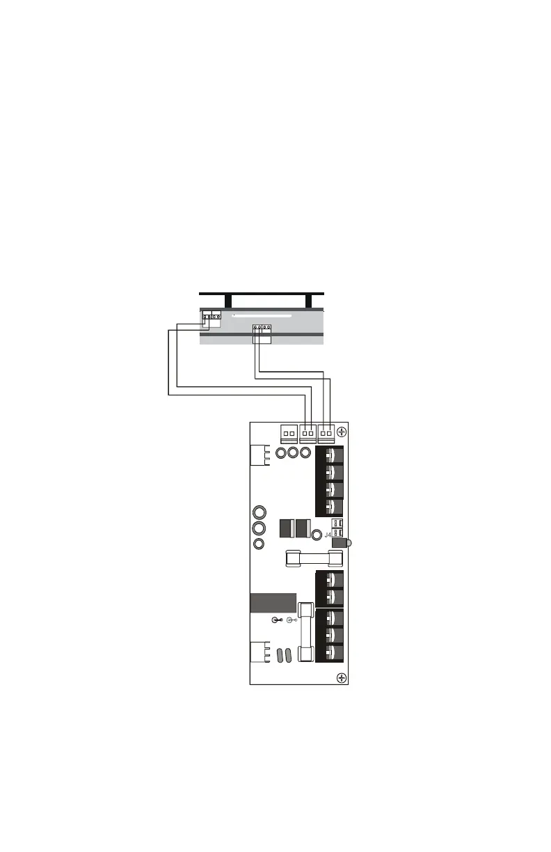
Connecting the APS-6R to an ICM/ICE Module
All four (4) NACs on the ICM are powered from the APS-6R output
circuit 2 (J2) and the four (4) NACs on the ICE are powered from
circuit 1 (J1). The NACs share the total 3A available from each circuit.
Typical connections for wiring:
Figure 7 Typical APS-6R Wiring to an ICM/ICE Module
J65 J
J65 J
J2
J9
J3
J1
TB2
JP3
JP2
ICM
ICE
Auxiliary Power
Harness
PN 71091
Black
Blue
Blue
Black
APS-6R
APS-6Ricm.cdr
www.PDF-Zoo.com