APPENDIX E - System 5000, AM2020/AFP-1010
26 PN 50702:B2 4/14/03
APPENDIX E - System 5000,
AM2020/AFP-1010
Mounting an APS-6R in a System 5000, AM2020 or
AFP-1010
An Auxiliary Power Supply is mounted on a CHS-4 Series chassis.
See “Mounting in CAB-3/CAB-4 Series Cabinets” on page 12.
Connecting the APS-6R to an MPS-24A
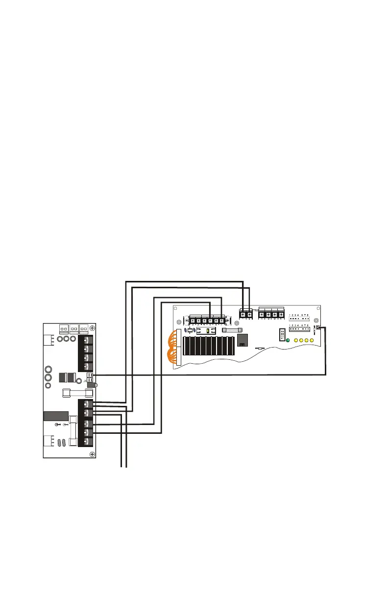
Make the following connections as shown in the figure below.
• Connect primary power from TB1 on the APS-6R to MPS-24A
terminal block TB1, Pin 5(
NEUT) and Pin 7(HOT).
• Connect secondary power from TB3 on the APS-6R to MPS-
24A terminal block TB2, Pin 1(+) and Pin 2(–).
• Connect trouble input from J3 on the APS-6R to MPS-24A
terminal block P5.
Figure 17 Wiring to MPS-24A
Connecting the APS-6R to an MPS-24BRB
The connections are the same as for the System 500. Refer to Page 25
in "System 500" for wiring instructions.
P4
P3
JP5
TB1
TB2
F1
CB1
P5
R27
P2
EARTH GND AC NEUTRAL AC HOT
+24R CO MMON +2 4 COMMON
POWER LIMITED
BAT + BAT -
J2
J9
J3
J1
TB2
JP3JP2
APS-6R to MPS-24A.cdr
To battery backup
+
-
www.PDF-Zoo.com