Section 1 Overview
8 PN 50702:B2 4/14/03
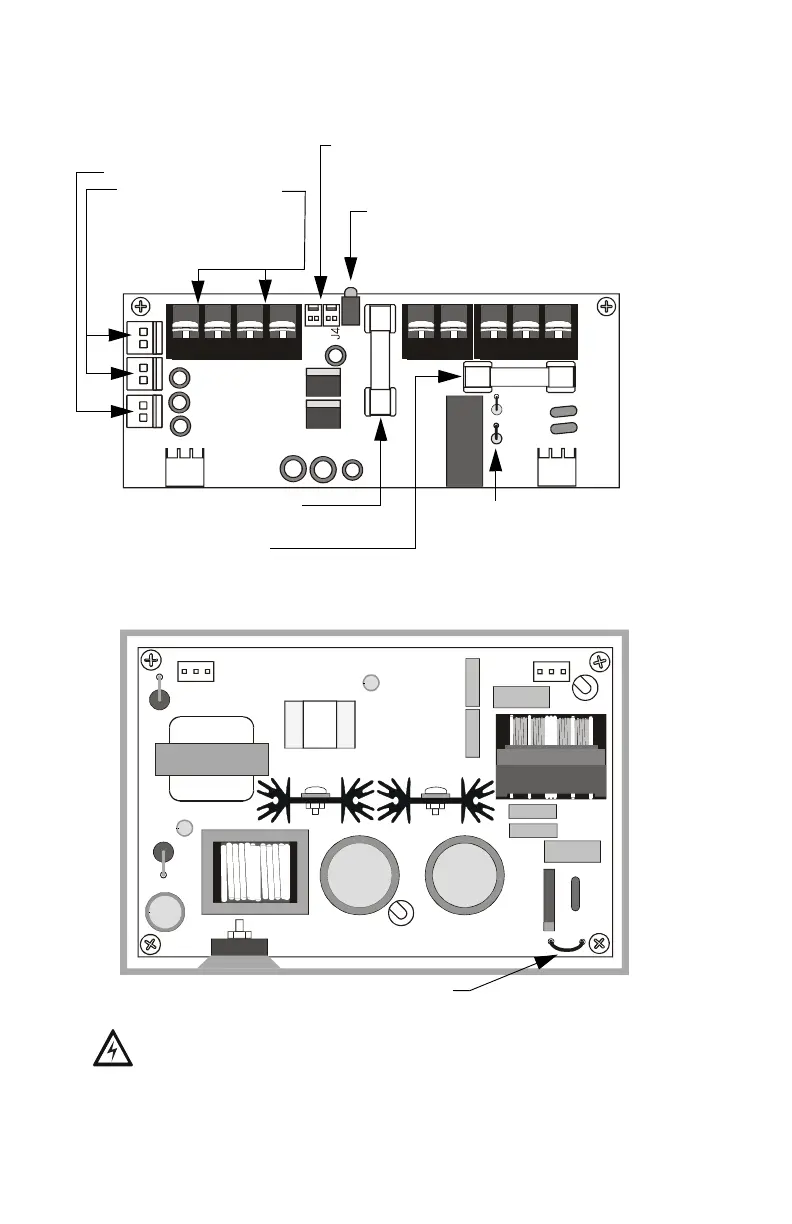
The figures below identify the features of the APS-6R power supply:
Figure 2 APS-6R Control Board
Figure 3 APS-6R Main Board
J2
J9
J3
J1
TB2
TB3
TB1
JP3
JP2
Fuse F1 for AC protection
(4A, 3AG, slow blow)
Three 24 VDC output circuits
One (1) non power-limited
Two (2) power-limited
(Refer to Figure 5 on page
page 14 for more specific
information on output circuits)
Trouble In (J4) - Trouble Out (J3)
“P” style connectors for internal cabinet
connections
LED Status Indicators:
Green LED – Indicates AC power on
Yellow LED – Indicates loss of AC or
battery
Fuse F2 for battery protection
(10A, 3AG, slow blow)
Jumpers JP2 and JP3 for selecting
8-hour or 16-hour delay for AC loss
reporting. Default is immediate. See
Page 18 in "Configuring the APS-6R".
APS-6Rsidebrd.cdr
JP1
Jumper JP1 for selecting AC input voltage
(120 VAC default). See Page 18 in "Configuring the APS-6R".
WARNING: HIGH VOLTAGE. For 240 VAC operation,
cut JP1 before connecting power.
APS-6Rboard.cdr
www.PDF-Zoo.com