PN 15037:D2 9/9/02 39
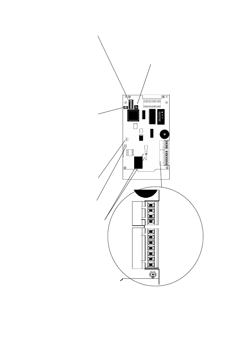
Figure 3-1 Configuring the LCD-80 for TERMINAL Mode
Note: Section 1.3 lists panels that support Terminal Mode.
Last LCD-80 Options (SW3)
These switches should be set
“OFF” for all LCD-80's except the
last on the EIA-485 loop.
1)
Set “ON” for the last LCD-80.
2)
Terminal Supervision - set “ON”
to supervise the EIA-
485 loop.
Ter
minal supervision must also be
enabled during program
ming
of the F
ACP.
Programming Key Interface
2-pin connector compatible
with PK-1 pr
ogram key.
AKS-1 Keyswitch Interface
Connect to optional keyswitch.
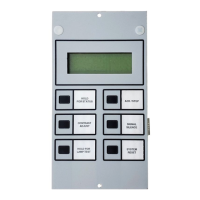
Operation mode Slide Switches
Set both switches in the DOWN position
(RAA 2020) for Terminal Mode.
SW2 - Not used in
TERMINAL Mode.
-pos
on
sw
c
1) Not used.
2) Not used.
3) Set “ON” to disable Piezo.
4) Set “ON” to disable
Acknowledge, Signal
Silence and Reset
sw
itches.
5) Not used.
6) Not used.
7)
Set “ON” in this mode.
8) Not used.
Terminal Mode Connections
- EIA-485 In
- EIA-485 Out
+ EIA-485 In
+ EIA-485 Out
No connection
No connection
System Common Ou
System Common In
+24 Volts Out
+24 Volts In
No connection
4
3
2
1
7
6
5
4
3
2
1
P1
P2
LCD80-board.tif