Installation and Operation Manual TFTN 085-199
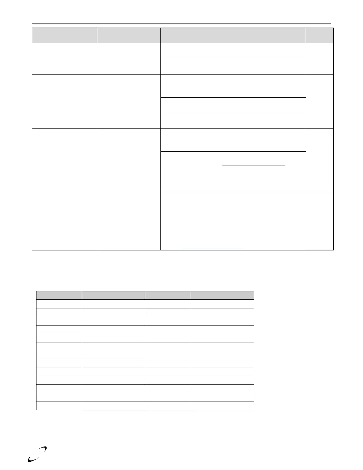
605 – Flue sensor open
circuit
Flue sensor reading is
invalid
Faulty wiring – check the wiring to the Flue sensor for
water or corrosion
Faulty sensor – check for proper readings from the Flue
sensor (see Table 18-2).
612 1 Fan Speed Too
Low Blower
Fan speed did not
achieve the correct
speed
Faulty wiring – check the 4-wire harness between the fan
and PCB for damage and check it for continuity. On the 3-
wire harness, verify 120VAC between black and white.
Faulty fan – remove the 4-wire harness from the fan, if it
does not run at high speed replace the fan.
Faulty PCB – if the wiring and fan are ok, replace the main
PCB.
Unconfigured – It’s
needed to configure the
device, press OK to
proceed
Boiler is configured as a
Follower, but it does
not see a Manager
boiler connected to the
BUS
Faulty wiring – if the boiler is a Follower in a cascade
system, check the BUS wiring to each boiler. Note: BUS
wiring is polarity sensitive.
Missing Manager – configure one of the boilers in cascade
as Manager; see section 11.0 - Cascade Installation.
Incorrect setting – if application is a stand-alone boiler,
set Boiler Address = Single Boiler. Press OK and select
Single boiler under Available Configurations
Incorrect settings – two or more boilers in the cascade
have been set with the same Boiler Address. Disconnect
each from the BUS and set a unique Boiler Address at
each boiler.
Multiple zone controllers with dip switches set to on –
there can only be two zone controllers connected to the
BUS, and only one can have the dip switches set to on; see
section 11.0 - Cascade Installation.
Table 18-2 Thermistor Resistance vs. Temperature