TFTN 085-199 Installation and Operation Manual
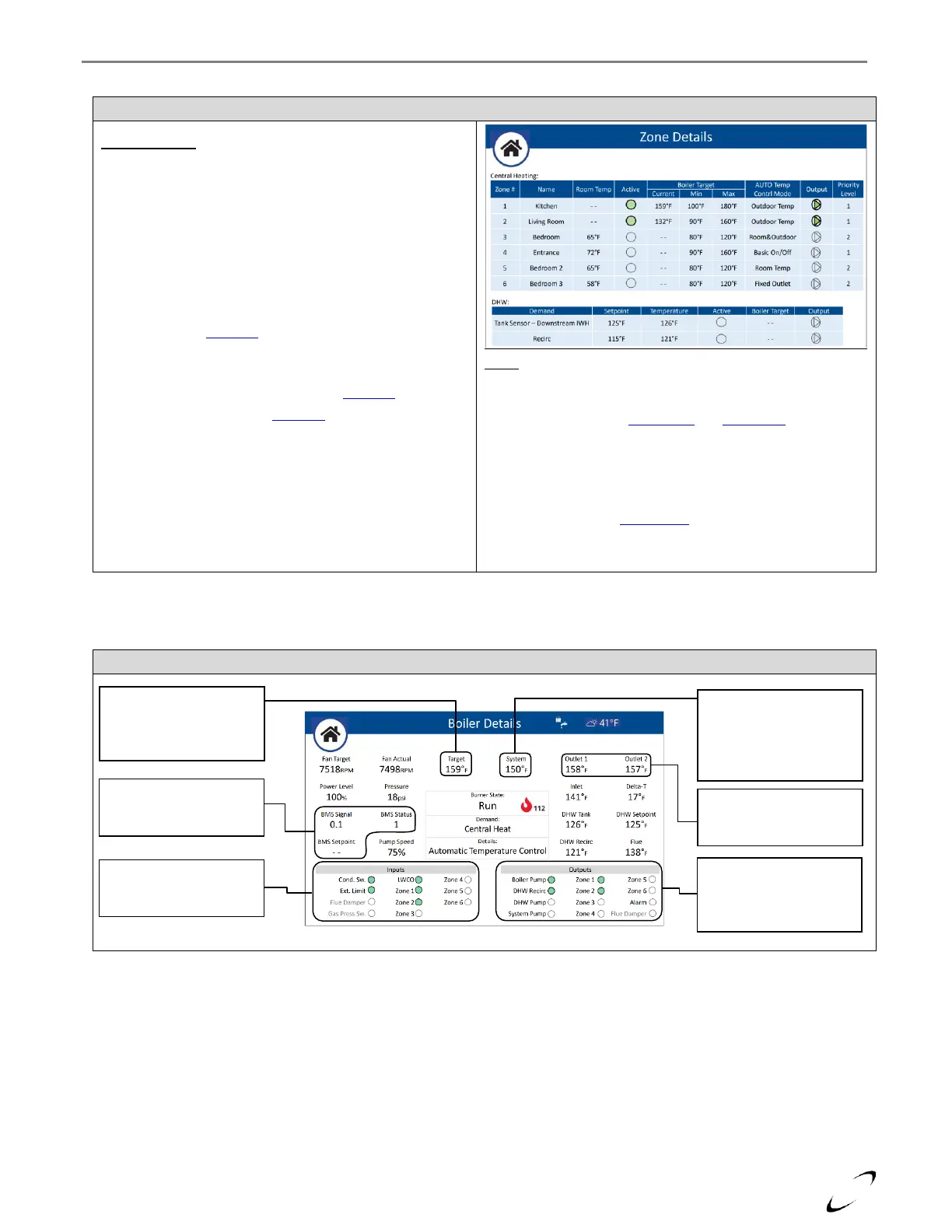
Figure 16-20 Zone Details Screen
Central Heating:
Lists the details and status of each of the CH zones. Note: Zone
# 4-6 correspond to zones 1-3 of a second zone controller
(applicable for cascade system or with N-link 3ZC).
Room Temp – current room temperature (only applicable for
zones using NTI Room Sensor)
Active – status of the zone input; turns green when the zone is
calling, and the Priority Level is current
Boiler Target – calculated (Current) boiler target temperature
and possible range (Min/Max) dictated by the given zone.
Adjustable via the CH Setup menu
Output – status of the zone output; turns green when the
output is switched on
AUTO Temp Contrl Mode – adjustable via CH Setup
Priority Level – adjustable via CH Setup -> Advanced Settings
DHW:
Lists the details and status of the DHW Demands, IWH (Tank Sensor
or Aquastat / Downstream or Upstream) and Recirc.
Setpoint – adjustable via DHW Setup and User Menu
Temperature – current temperature readings from DHW
SWITCH/NTC and AUX2 NTC
Active – status of the demand; turns green when calling
Boiler Target – boiler target temperature dictated by the given
zone. Adjustable via DHW Setup -> Advanced Settings option
Modulation Setpoint. Not applicable for DHW Recirc.
Output – status of the DHW and DHW Recirc pumps.
Figure 16-21 Boiler Details Screen
Target – select to have the
system walk you through a
step-by-step setup
procedure of the controller
BMS – only applicable
when BMS Control Mode is
set to 0-10V (Power/Temp)
Inputs – gives the status of
each of the boiler’s on/off
inputs
System – only visible when
a sensor is connected to
AUX1 NTC and Auxiliary
Sensor 1 is set to System
Sensor
Outlet 1,2 – readings from
the boiler’s duplex outlet
sensor
Outputs – gives the status
of each of the boiler’s
on/off outputs, green
means on