NOTES:
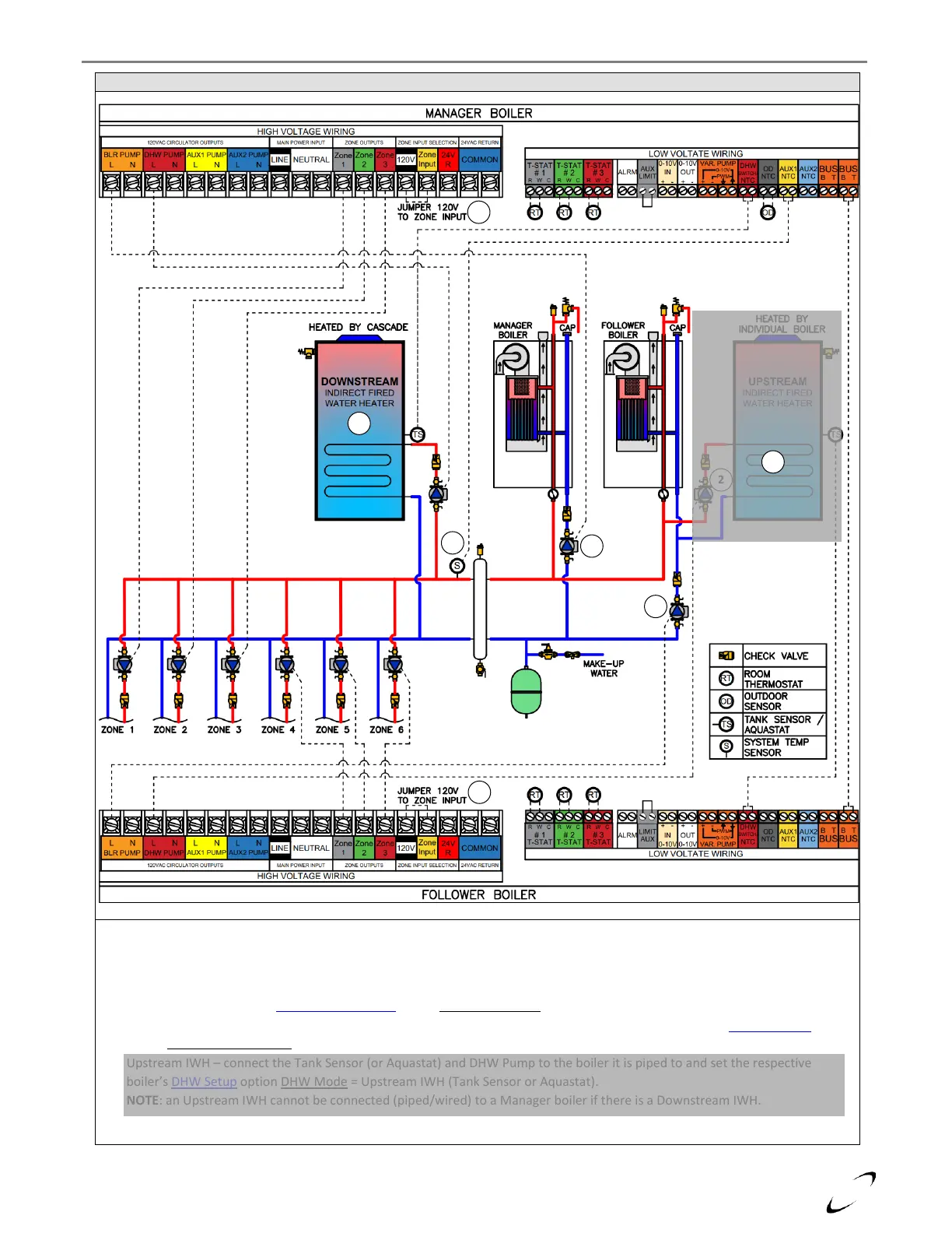
1. For ZONE 1, ZONE 2 & ZONE 3 to output 120VAC (like in this example), jumper ZONE INPUT to 120V.
2. Pumps responsible for circulating water through the boiler must be sized accordingly (see Tables 10-2 & 10-3).
3. System Sensor – mandatory in cascade configurations; must be installed downstream of the LL-header. Connect to AUX1 NTC
at Manager boiler and set Sensor Configuration option Auxiliary Sensor 1 (24.6.1) = System Sensor.
4. Downstream IWH – connect the Tank Sensor (or Aquastat) and DHW Pump to the Manager boiler and set Cascade Setup
option DHW Mode (Cascade) = Downstream IWH (Tank Sensor or Aquastat).
5. Upstream IWH – connect the Tank Sensor (or Aquastat) and DHW Pump to the boiler it is piped to and set the respective
boiler’s DHW Setup option DHW Mode = Upstream IWH (Tank Sensor or Aquastat).
NOTE: an Upstream IWH cannot be connected (piped/wired) to a Manager boiler if there is a Downstream IWH.