NewsCaster VT2 Features
M17-0002-01A Rev 0.0 12 User Manual
The parts lists and drawings in this manual are specific to this unit.
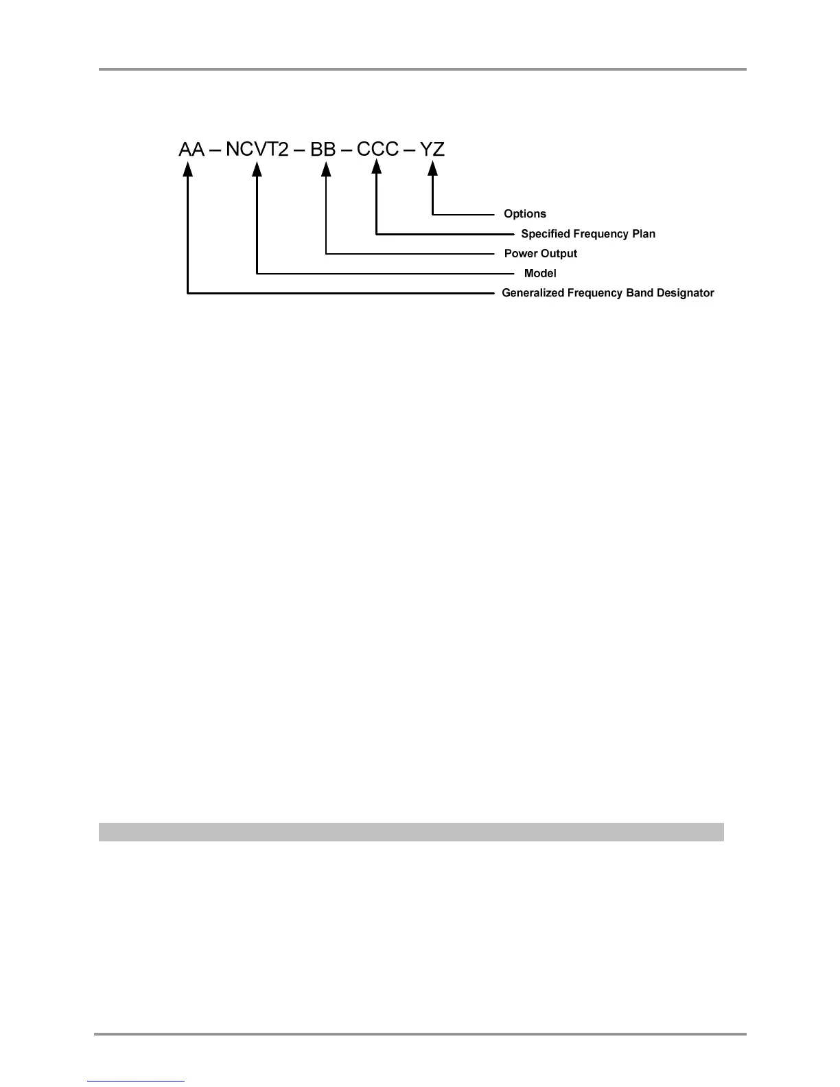
Where as:
AA = mean frequency band centered in GHz, rounded to the closest GHz. This number is then
multiplied by 10. For multiple bands, each center frequency designation is separated by a backslash
(/).
BB = Used to identify the power output, per the following Power Output Designators:
Power Output is represented by Letters (A-Z; A=1, B=2, C=3, etc) for the analog power, and
Numbers (0-9) for the digital power. For example, a 5W Analog / 2W digital system would be
described with a power indicator of "E2". A Dual-Band system would have two sets of power
indicators, to show the power levels at both bands.
CC = Nucomm assigns a frequency chart number for each unique frequency channel combination.
Contact your Nucomm representative for further information.
X = Type Emphasis; 1 = NTSC and PAL M; 2 = PAL B/G
YZ = Miscellaneous options as listed below (append as many letters as needed)
G = 160 VDC Pan & Tilt
G1 = 12 VDC Pan & Tilt
I = Four Contact Closures
J = NSI Antenna
K = Radio Waves Antenna
U1 = 90 to 260 VAC
U3 = 11 to 15 VDC
M = FM only
M1 = COFDM only
M2 = FM / COFDM
M3 = FM / COFDM / DVBS
M4 = COFDM / DVBS
M5 = DVBS only
M6 = External 70MHz
Options that are not a standard part of the system, will be shown by shaded text as shown here.