Home
Nuomm
Transmitter
NEWSCASTER VT2
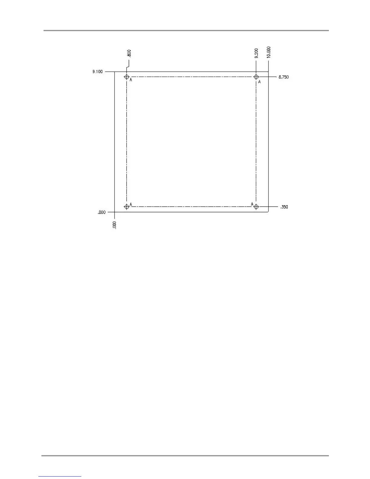
Page 36 (Figure 13: Hole Pattern of RF Head Base Plate)
Nuomm NEWSCASTER VT2 - Figure 13: Hole Pattern of RF Head Base Plate
72 pages
Manual
Save Page as PDF
To Next Page
To Next Page
To Previous Page
To Previous Page
Loading...
NewsCaster VT2
Installation
M17-0002-01A Rev 0.0
36
User Manual
Figure 13
:
Hole Pattern of RF H
ead Base P
late
Drill holes (A) are .250 Dia. (through drilled)
Material is ALUM 6061, ¼” thick.
Use four (4) size ¼-20 x .750” screws to mount the unit.
35
37
Table of Contents
Main Page
Default Chapter
5
Fcc Statement
5
Table of Contents
6
1 Description
11
Figure 1: Newscaster VT2 System Diagram
11
2 Features
13
Figure 2: Newscaster VT2, Simple Block Diagram
13
Figure 3: Control Unit Block Diagram
14
Figure 4: RF Head Block Diagram
17
3 Specifications and Frequency Plans (USA)
19
Frequency Plans (USA)
23
Table 1: Frequency Plan (US), 2 Ghz 17 Mhz
23
Table 2: Frequency Plan (US), 2 Ghz 12 Mhz
24
Table 3: Frequency Plan (US), 7 Ghz
25
Table 4: Frequency Plan (US), 12 Ghz
26
Table 5: Frequency Plan (US), 13 Ghz
27
4 Installation
29
Unpacking & Inspection
29
Pre-Installation Checkout
29
Cables and Connectors
29
Control Unit Mechanical Installation
29
Figure 5: Control Unit Front Panel
30
Figure 6: Control Unit Rear Panel (AC Model)
31
Control Unit Electrical Installation
32
Figure 7: Control Unit, Audio Connector
32
Figure 8: Control Unit, RS-232 Connector
33
Figure 9: Control Unit, Joystick Connector
33
Figure 10: Control Unit, 160V Pan/Tilt Power Connector
34
Figure 11: Control Unit, 12 VDC Pan/Tilt Power Connector
34
RF Head Mechanical Install
35
Figure 12: Mounting RF Head Using Mounting Plate
35
Figure 13: Hole Pattern of RF Head Base Plate
36
Preparing the Interconnect Cables (Including Nycoil)
37
Figure 14: Nycoil Block Diagram - Standard Coax (or Triax) Configuration
37
Figure 15: Nycoil Block Diagram - Alternate Coax Configuration
37
Table 6: Recommended Nycoil Cable Lengths
37
Table 7: Typical if Cable Configurations for the Newscaster VT2
38
Table 8: AUX Power Cable Pin-Out
38
Figure 16: Pan & Tilt Power (120VAC) Interconnect Diagram
39
Table 9: Pan & Tilt Power (120 VAC) Connector Pin-Outs
39
Figure 17: Pan & Tilt Power (12 VDC) Interconnect Diagram
40
Table 10: Pan & Tilt Power (12 VDC) Connector Pin-Outs
40
Figure 18: Pan & Tilt Motor Interconnect Cable
41
Table 11: Quickset QPT90 12 VDC/120 VAC Pan & Tilt Connector Pin-Out
41
Figure 19: NSI Quad Antenna Polarization Connections
42
Table 12: NSI Quad Antenna Polarization Connector Pin out
42
Figure 20: Radio Waves Quad Antenna Polarization Connections
43
Table 13: Radio Waves Quad Antenna Polarization Connector Pin out
43
RF Head Connectors
44
Figure 21: RF Head, Front-Panel (Shown W/Pan & Tilt Option)
44
Figure 22: RF Head AUX Power Connector
45
Figure 23: RF Head, Rear Panel
45
Figure 24: TNC and TRIAX Connectors
45
Control Unit / RF Head Interconnect
46
Figure 25: NCVT2 Interconnects
46
5 Operation
49
Front Panel Operation
49
Figure 26: NEWSCASTER VT2 Front Panel Controls and Indicators
49
Figure 27: Menu Buttons
49
Controls and Indicators
50
Upper Level Menu
53
Table 14: COFDM Data Rates (8 Mhz Bandwidth)
56
Table 15: COFDM Data Rates (7 Mhz Bandwidth)
56
Table 16: COFDM Data Rates (6 Mhz Bandwidth)
57
Table 17: VSB Data Rates
58
Figure 28: Antenna Button
60
Nextel BAS Relocation Settings
64
Audio Sub-Carrier Frequency
64
Channel Bandwidth and Band Plan
65
Switchover to "Post-Nextel" Settings
65
Troubleshooting Guide
66
Table 18: Newscaster VT2 Alarms
66
Multiple Alarms
69
NCVT2 Control Unit Front Panel (C132)
69
Figure 29: Menu Tree (Continued)
70
Figure 30: Menu Tree
71