NewsCaster VT2 Installation
M17-0002-01A Rev 0.0 33 User Manual
Audio
The Analog and Digital audio inputs are made
via a strip terminal on the rear panel. (Refer
to Figure 6, Detail 6 for connector location.)
The terminal marked "G" is for the ground
lead, (–) is for the negative signal and (+) is
for the positive. (Refer to Figure 7 for the
connector detail.)
The Digital AES/EBU inputs are made via the
Audio 1 & Audio 3 terminals. As such, only
one Digital audio is available in the standard
“two audio” configuration.
IF Interface and AUX Power
When the IF Cable is suitable, a single TNC
(or optional Triax) connector (Figure 6,
Detail 7) is used to output the three signals
that must pass between the Control Unit and
the RF Head. These are:
(a) Modulated 70 MHz signal
(b) Inter-unit control data
(c) +48VDC for the RF Head.
For cases when an existing non-conforming IF
cable that cannot handle +48 VDC, the AUX
Power option must be fitted on, which will
provide the +48V on a separate connector
(Figure 6, Detail 5) for transport to the RF
Head via dedicated conductors.
Table 7 lists conforming cables and details the
various configurations possible with and
without the AUX Power option.
NOTE: When AUX Power is configured, the
+48 VDC still remains available at the IF
Interface port. This allows the user to
upgrade to a conforming IF cable without
requiring any changes to the unit.
Additional detailed information on the
interconnection between the Control Unit and
RF Head is found in Sections 4.7 – 4.9.
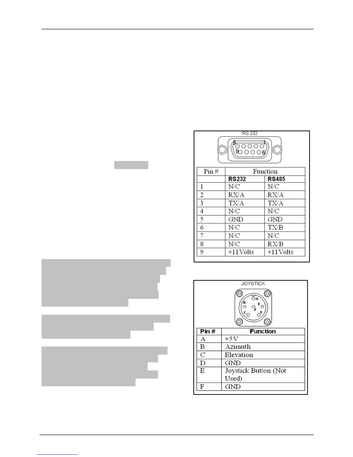
Remote
The remote control port (Figure 6, Detail 8)
allows for full control and monitoring of the
NewsCaster VT2. Both RS232 and RS485 are
supported. Refer to Figure 8 for pin-out.
Figure 8: Control Unit, RS-232 Connector
Figure 9: Control Unit, Joystick Connector