UM11158 All information provided in this document is subject to legal disclaimers. © NXP B.V. 2019. All rights reserved.
User manual Rev. 1.2 — 25 April 2019 5 of 24
NXP Semiconductors
UM11158
LPCXpresso55S69 Development Board
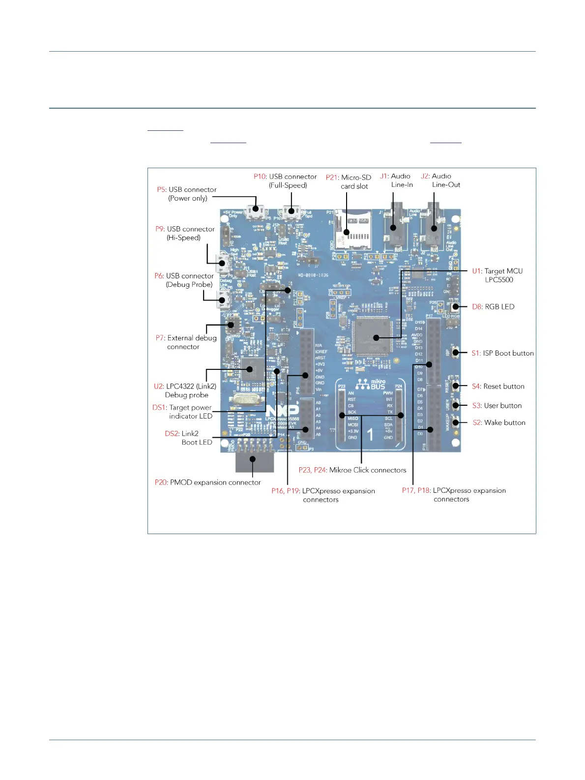
2. Board layout and Settings
Figure 2 shows the layout of the board (top side), indicating location of the connectors and
buttons, while Figure 3 shows locations of jumpers and headers. Table 1 provides a
description of connectors, jumpers, LEDs and buttons.
Fig 2. LPCXpresso55S69 connectors and buttons

 Loading...


