3. ENGINE
3-
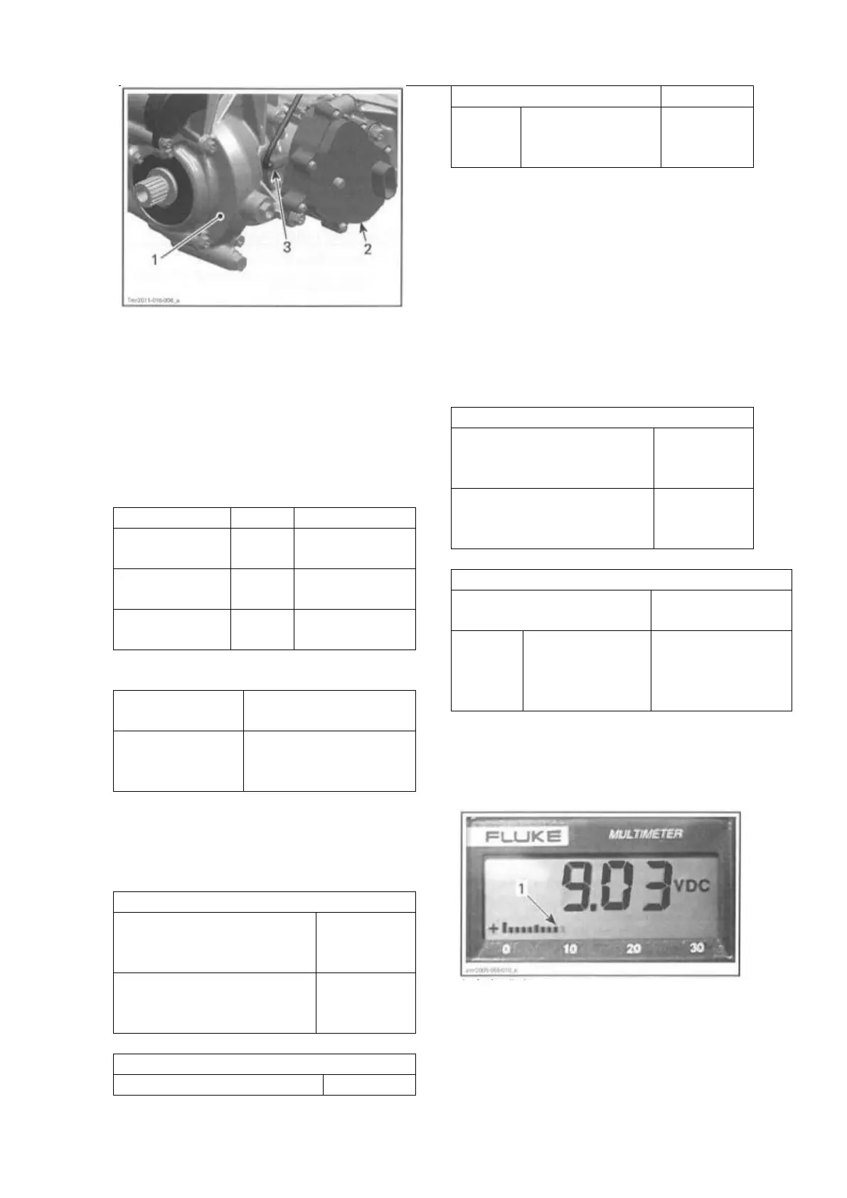
1. Tight housing of gearbox
2. Actuator
3. VSS (Vehicle Speed Sensor)
VSS Access
To reach the VSS, remove the following parts
- Passenger seat
- RH lateral console panel
- Fuel tank cowl.
VSS Wire Identification
12-volt input
from fuse F5
Speed signal
(to ECM-A E1)
VSS Circuit Protection
Supplied with
main
relay activated
Fuse5 of fuse block1
(from main relay R2)
VSS Input Voltage Test
1. Turn ignition switch 0N.
2. Back-probe the VSS connector and measure
voltage.
BACK PROBE TEST
WIRES
(P/N529 036 063)
FLUKE115
MULTIMETER
(P/N529 035 868)
If voltage is not as specified, test positive and
ground separately.
VSS Signal Test
1. Lift rear of vehicle so that rear wheels are off
the ground.
2. Set transmission to2WD and to Neutral.
3. Turn ignition switch 0N.
4. Back-probe the VSS connector and measure
voltage while slowly rotating rear wheels by
hand.
BACK PROBE TEST
WIRES
(P/N529 036 063)
FLUKE115
MULTIMETER
(P/N529 035 868)
Alternate reading
between battery
voltage and 0 Vdc
NOTE: Since we measure pulsating voltage,
the numeric display will continuously change.
The analog display may be easier to follow.
1. Analog display