3. ENGINE
3-
Clean the valve guide bore before reinstalling the
valve guide into cylinder head.
Install valve guide.
1. Valve guide installer
2. Valve guide
NOTE: Apply LOCTITE767 (ANTISEIZE
LUBRICANT) (P/N293 800 070) on valve guide
prior to install it into the cylinder head.
NOTICE Push valve guide in the cold cylinder
head as per following illustration.
1. Thrust surface of cylinder head
2. Valve guide
A. Measurement from thrust surface to valve guide
top
VALVE GUIDE(MEASUREMENT“A”)
14.00mm to14.40mm
(.5512 in to .5669 in)
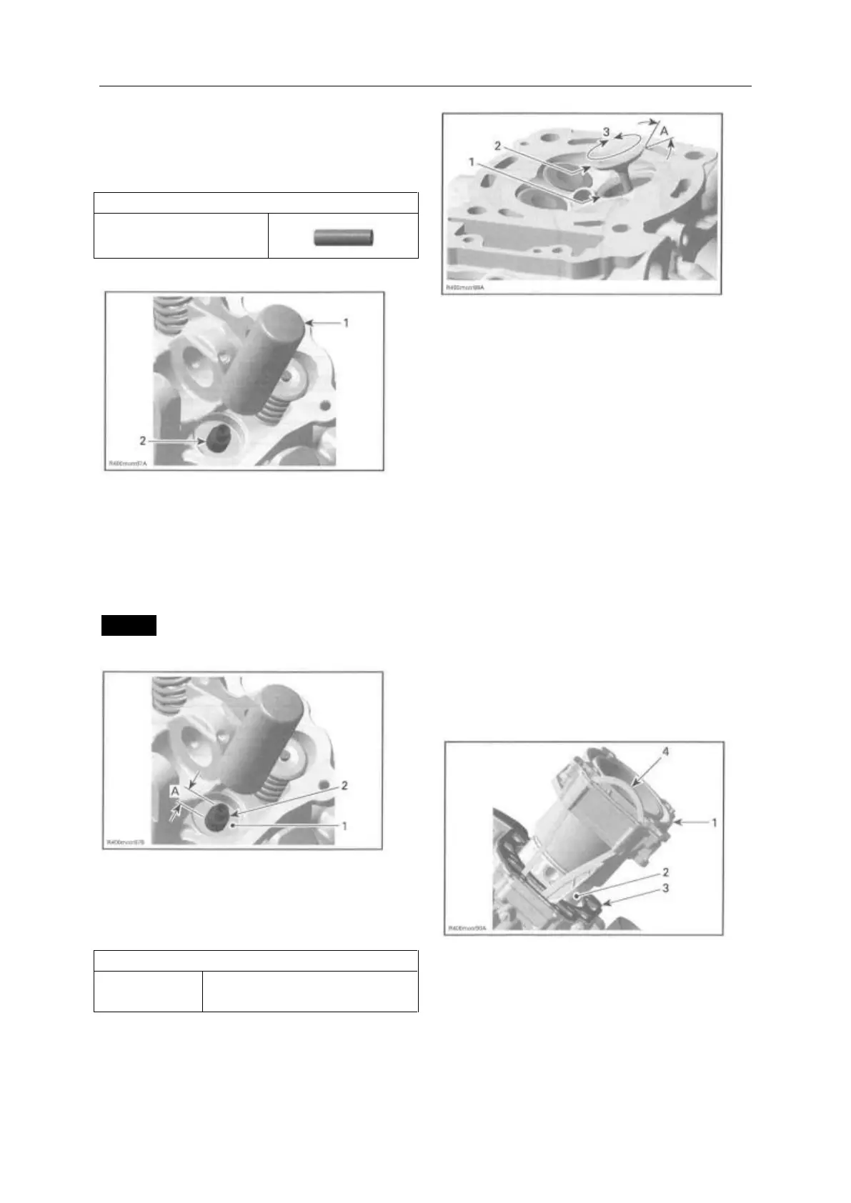
Apply some lapping compound to valve face and
work valve on its seat with a lapping tool.
1. Valve seat
2. Valve face (contact surface to valve seat)
3. Turn valve while pushing against cylinder head
A. Valve seat angle 45°
NOTE: Ensure to seat valves properly. Apply
marking paste to ease checking contact pattern.
Repeat procedure until valve seat/valve face fits
together.
CYLINDER
Cylinder Removal
Refer to TUMING CHAIN subsection and remove
the following parts:
- Timing chain tensioner
- Camshaft timing gear.
Remove the cylinder head (see CYLINDER
HEAD in this subsection).
Pull cylinder.
Discard cylinder base gaskets.
1. Cylinder
2. Piston assembly
3. Cylinder base gasket
4. Camshaft timing chain