44
Horizontal and built-under fresh-water storage
tanks 120 – 500
7.10
Fresh-water, Combined and Buffer Storage Tanks
GB
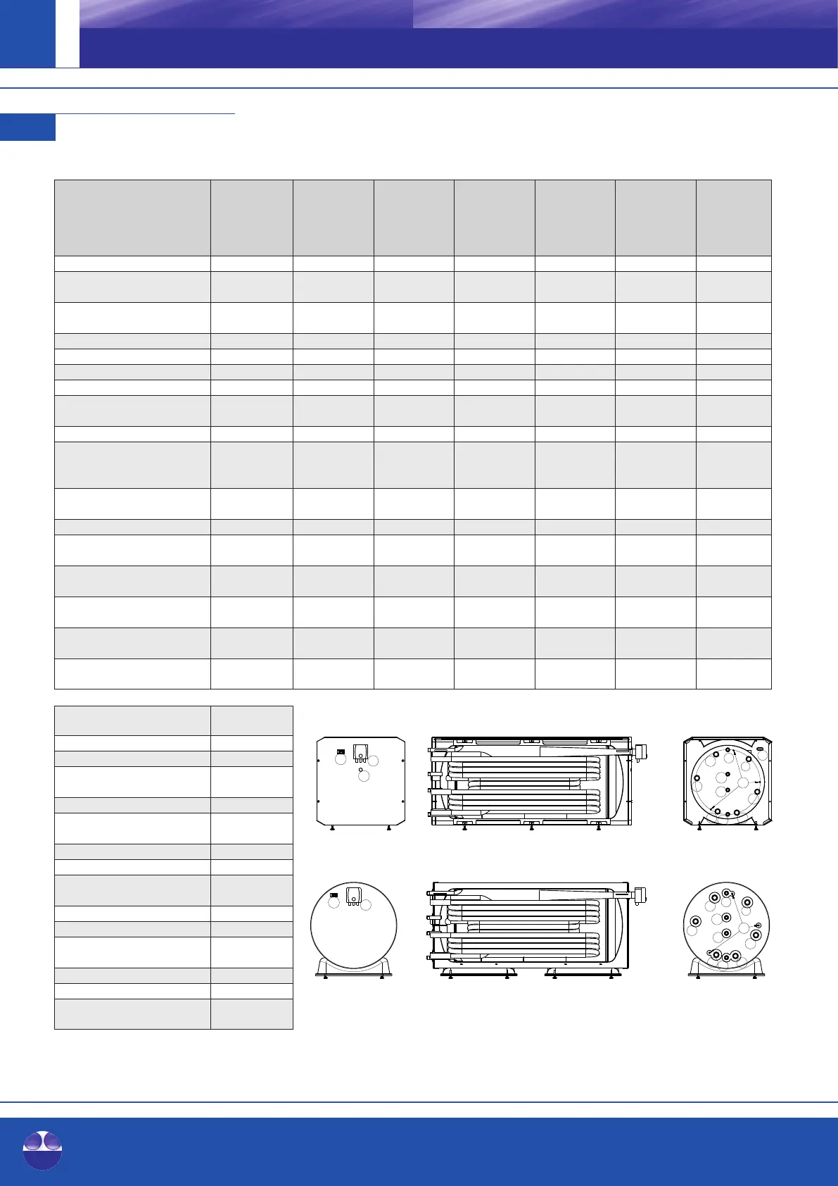
Horizontal and built-under
fresh-water storage tanks without,
with one (-1) or with two (-2) 120 / 120-1 / 150 / 150-1 / 200 / 200-1 / 300 / 300-1 / 400 / 400-1 / 500 / 500-1 /
additional heat exchangers 120-2 150-2 200-2 300-2 400-2 500-2
Real volume according
to EN 12897 [l] 117 / 116 / 115 157 / 156 / 155 206 / 205 / 204 301 / 300 / 298 455 / 454 / 452 498 / 496 / 494
Fire protection class of insulation
according to DIN 4102-1 [-] B2 B2 B2 B2 B2 B2
Total height* including insulation [mm] 700 700 700 700 850 850
Width [mm] 610 610 610 610 760 760
Length [mm] 785 995 1,260 1,750 1,600 1,730
Weight [kg] 55 / 60 / 65 65 / 72/ 79 79 / 87 / 96 103 / 111 / 120 123 / 136 / 150 141 / 154 / 167
Energy efficiency class according
to EU regulation no. 812/2013 [-] A+ A+ A+ A+ A+ A+
Heat retaining loss according to EN 12897 [W] 26 29 31 36 41 43
Output capacity 45°C
(storage tanks 65°C,
cold water 10°C, no reheating) [l] 70 85 115 175 230 290
Performance factor NL
following DIN 4708 [-] 0.8 1 1.2 1.6 2 3
Storage tank pmax / tmax [bar] / [°C] 3 / 95 3 / 95 3 / 95 3 / 95 3 / 95 3 / 95
DHW heat exchanger
surface / volume [m²] / [l] 1.52 / 6.92 2.1 / 9.6 2.5 / 11 2.5 / 11 5.1 / 23 5.1 / 23
DHW heat exchanger
pmax / tmax [bar] / [°C] 6 / 95 6 / 95 6 / 95 6 / 95 6 / 95 6 / 95
Additional heat exchanger**
bottom surface / volume [m²] / [l] 1 / 4.69 1.4 / 6.2 1.7 / 8 1.7 / 8 3 / 14 3 / 14
Additional heat exchanger**
top surface / volume [m²] / [l] 1 / 4.55 1.4 / 6.1 1.7 / 8 1.7 / 8 3 / 14 3 / 14
Additional heat exchanger**
pmax / tmax [bar] / [°C] 6 / 95 6 / 95 6 / 95 6 / 95 6 / 95 6 / 95
Return additional heat
exchanger bottom** (Rp 1¼") A [mm]
Return heat generator (R 1") B [mm]
Cold water connection (Rp 1¼") C [mm]
Flow additional heat exchanger**
bottom (Rp 1¼") D [mm]
Freely available (R 1") E [mm]
Return additional heat
exchanger** top (Rp 1¼") F [mm]
Freely available (R 1") G [mm]
Sensor sleeve*** (Ø 6 mm) H [mm]
Flow additional heat exchanger**
topn (Rp 1¼") I [mm]
Flow heat generator (R 1") J [mm]
Hot water connection (Rp 1¼") K [mm]
Sensor cable feed-through
(45x18 mm) L [mm]
Thermometer (clip) M [mm]
Heating element (Rp 1½") N [mm]
cable feed-through heating
element (Ø 26 mm) O [mm]
* feet adjustable by ±13mm
** if there is one
*** Caution: Install the temperature sensors before mounting the steel jacket.
Use the sensor cable feed-through (L) for guiding the temperature sensors.
A
B
C
D
E
F
G
K
I
L
M
J
N
O
A
B
C
D
E
F
G
I
J
K
M
N
H
H