CHAPTER 2 DIAGNOSTIC GUIDE
Valor™ 2000 Series Service Manual 2-3 Ohaus Corporation www.ohaus.com
2.2.2 Checking Load Cells for Trouble
– Measure the voltages on +SIG and –SIG wires, disconnected from PCB.
Note: Measurements must be made with these wires disconnected from the
PCB. These measurements represent the output of the Load Cell. Record
measurements at Zero Load, 50% and full scale capacities. See Table 2-3 for
typical readings.
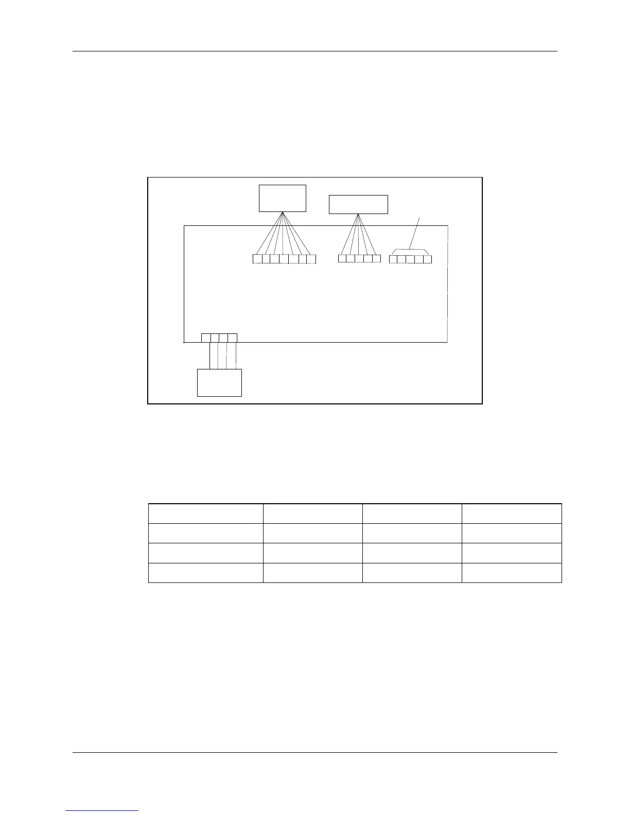
TOP VIEW OF PCB
1
2
3
4
EXE+
EXE–
SIG–
SIG+
Load
Cell
1
2
3
4
5
6
7
AC &
Battery
Connector
1
2
3
4
5
Rear Display
PCB Connector
1
2
3
4
5
(Not used)
Figure 2-1. Valor 2000 PCB connections
NOTE: Table 2-3 indicates typical readings. Actual values can vary, but should
remain linear throughout the range. If readings are out of tolerance, replace the
Load cell. (See Section 3.6.)
TABLE 2-3. LOAD CELL OUTPUT READINGS (in mV with 5V Excitation)