Chapter 4 41
Installation
C
W
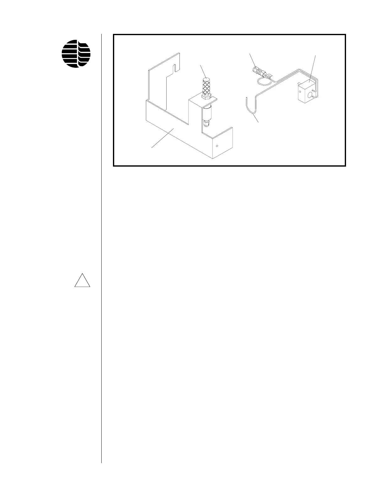
Figure 4.9. Needle Valve Assembly and OIM Gas Outlet Block Assembly
Fine Adjust
Needle Valve
Needle Valve Bracket
WALL Gas Line
Union Fitting
OIM Gas
Outlet Block
To COMB Fitting on
Bottom of Needle Valve
17. Using needle-nosed cutters, remove the appropriate detector cutout from the
top back panel of the GC.
18. Replace the top back panel on the GC.
19. Remove the protective caps from the gas inlets on the front of the OIM gas
flow module. Using Q/i" brass nuts and ferrules, attach the H
2
gas line to the
inlet labeled “H
2
”, an air line to the inlet labeled “Air 1”, and another air line
to the inlet labeled “Air 2” (see Figure 4.8).
20. Gently turn the fine adjust needle valve (Part #282491) to the OFF position
(clockwise) (see Figure 4.7). Do not excessively tighten down—this can
damage the needle valve. Then open two full turns counterclockwise.
21. Replace the flame arrestor located on top of the detector cap with the barbed
fitting (Part #202077) included in the PFPD Start-up Kit. Attach a gas flow-
meter to the barbed end of the fitting.
22. Open the supply cylinder valves regulating the air and H
2
gas supply to the
GC. Turn on the GC.
23. Using the GC’s control module, turn the detector flow rates to zero. Confirm
that there is no flow.
24. If using a 2-mm combustor, use the GC’s front panel to set H
2
(PFPDH
2
) to
11.5 mL/min for sulfur mode or 9.0 mL/min for phosphorus mode; Air 1
(PFPD AIR) to 10 mL/min; and Air 2 (MAKEUP) to 10 mL/min. After each
setting, use the flowmeter to confirm the flow rates. Once these flow rates
have equilibrated, do not make any further adjustments to the flow settings
until you are ready to optimize the operating parameters of the PFPD (see
Chapter 5, “Operation”).
!
CAUTION: Do
not use the
needle valve as
an On/Off valve.
Overtightening
can distort the
needle valve’s
seal and make it
unreliable.