44205401TH Rev.1
162 /
Oki Data CONFIDENTIAL
7. Troubleshooting and repair procedure
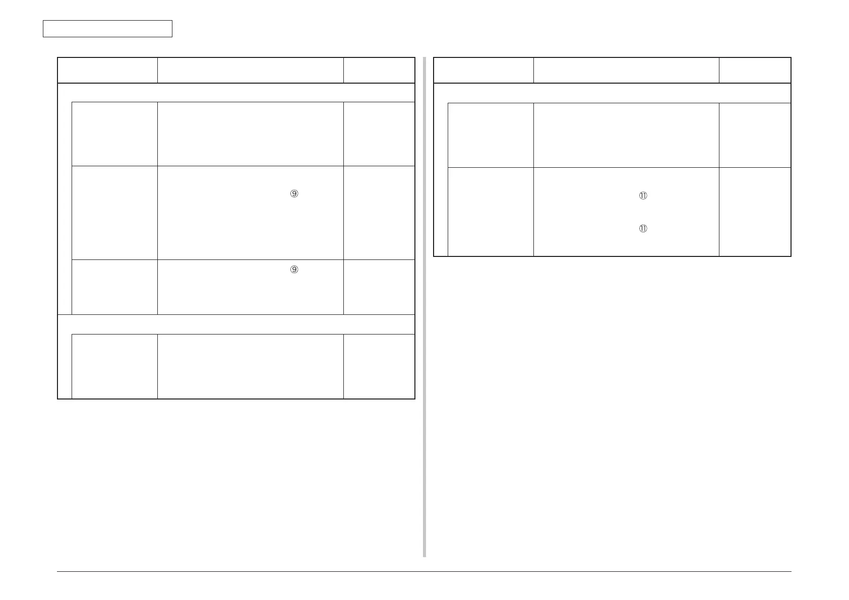
Check item Check work
Action to be taken
at NG
(3-2-4) Check the system connection
Paper feed motor
drive cable
Check the connection condition of the cable.
Check if the connector is connected in the half-
way only or not, and check if the connector
is inserted in a slanted angle or not. Check
also that cables are assembled without any
abnormality.
Replace the
cable with the
good cable
that normalizes
the connection
condition.
Paper feed motor
drive cable
Check that any cable is not pinched during
assembling of the printer.
Remove the HP_PSZCL connector
of the CU/
PU board and check the followings at the cable
side.
Short circuit between pin-1 – FG
Short circuit between pin-2 – FG
Short circuit between pin-3 – FG
Short circuit between pin-4 – FG
Replace the
cable with the
good cable
that normalizes
the connection
condition.
Paper feed motor Remove the HP_PSZCL connector
of the CU/
PU board and check that approx. 3.4
Ω
can be
measured between pin-1 -pin-2 at the cable end,
and that approx. 5
Ω
can be measured between
pin-3 -pin-4 respectively.
Replace the
paper feed motor.
(3-2-5) Solenoid operation check
Paper feed clutch Confirm that the paper feed clutch or regist
clutch works normally by using the Motor &
Clutch Test of the self-diagnostic mode.
Remove the metal plate from the right side of a
printer so that the clutch becomes visible. Then,
chec
k operation of the clutch
.
Replace the
CU/PU board,
or replace the
paper feed
clutch or regist
clutch.
Check item Check work
Action to be taken
at NG
(3-2-6) Check the system connection
Paper feed clutch
cable
Chec
k the connection condition of the cable.
Check if the connector is connected in the half-
way only or not, and check if the connector
is inserted in a slanted angle or not. Check
also that cables are assembled without any
abnormality.
Replace the
cable with the
good cable
that normalizes
the connection
condition.
Paper feed clutch
cable
Check that any cable is not pinched during
assembling of the printer.
Remove the CL1 connector
of the CU/PU
board and check the followings at the cable side.
Short circuit between pin-1 – FG
Remove the CL1 connector
of the CU/PU
board and check that approx. 240
Ω
can be
measured between pin-1 and pin-2.
Replace the
solenoid and re-
assemble the
printer correctly.