- 14 -
Operator Panel
1
1. Setup
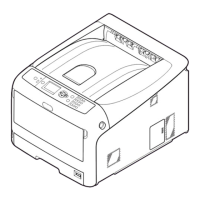
Names of Components
1
2
3
4
5
6
7
8
8
No. Name
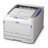
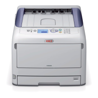
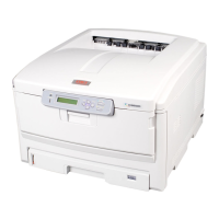
1 Front cover
2 Front cover open lever
3 Operator panel
4 Power switch
5 Output tray
6 Multipurpose tray
7 Tray 1
8 Air vents
9
10
11
12
13
14
15
No. Name
9 Output tray open button
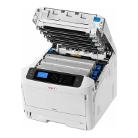
10 Toner cartridge
Image drum (K: black)
11 Toner cartridge
Image drum (Y: yellow)
12 Toner cartridge
Image drum (M: magenta)
13 Toner cartridge
Image drum (C: cyan)
14 Fuser unit
15 LED head (four heads)
Note
● In the case of the ES models, toner cartridges are not
installed in the Image drums.
16
17
26
No. Name
16 Multipurpose tray
17 Paper set cover
26 Wireless LAN module cover
18
22
19
20
21
No. Name
18 Rear output tray
19 AC power socket
20 Interface part
21 Access cover
22 Duplex unit (Only for the model of the name
with dn or ES)
● Interface part
23
24
25
No. Name
23 Accessory connector
24 USB interface connection
25 Network interface connection