EasyManuals Logo

Oki MICROLINE 320 Turbo Maintenance Manual

Oki MICROLINE 320 Turbo
123 pages
To Next Page IconTo Next Page
To Previous Page IconTo Previous Page
Page #53 background imageLoading...
Page #53 background image
42089201TH Rev.4 53 /
Oki Data CONFIDENTIAL
[How to Change Parts]
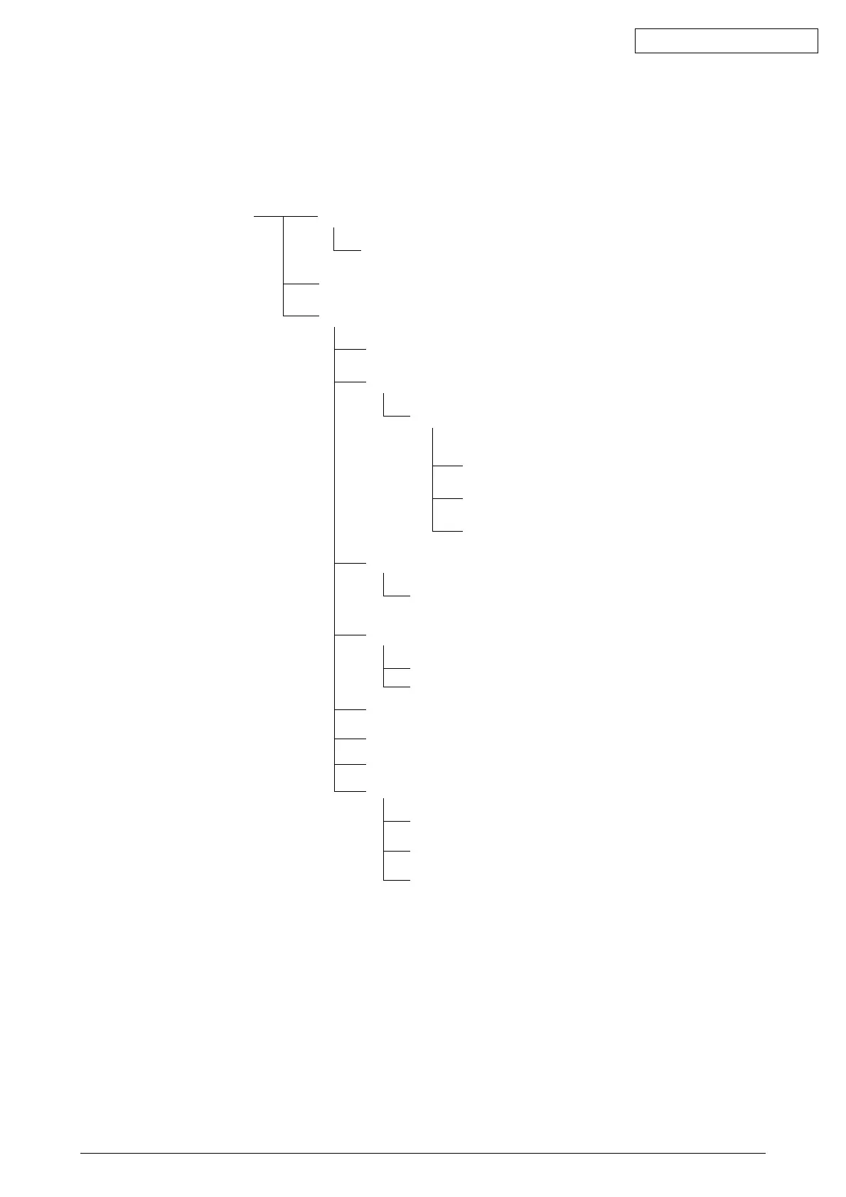
This section explains how to change parts and assemblies appearing in the disassembly diagram
below.
Printer unit
3.3.1 Printhead
3.3.2 Ribbon protector
3.3.3 Pull-up roller assy
3.3.4 Upper cover, access cover and sheet guide
3.3.5 Gear case assy
3.3.6 PC connector
3.3.7 Space motor and guide roller assy
3.3.8 Space rack
3.3.9 Carriage cable
3.3.10 Back-up roller holder assy
3.3.11 Platen assy
3.3.19 Paper pan
3.3.12 Driver board (DVF/DVE or SDF)
3.3.13 LF motor
3.3.18 Carriage shaft
3.3.14 Operation panel PCB (LEOP)
3.3.15 Control/Power supply board (AOO/AOU or AOE)
3.3.16 Transformer assy
3.3.17 Change lever and gears
3.3.20 Rear tractor assy
3.3.21 Rear pressure assy
3.3.22 Switch lever

Table of Contents

Other manuals for Oki MICROLINE 320 Turbo

Questions and Answers:

Question and Answer IconNeed help?

Do you have a question about the Oki MICROLINE 320 Turbo and is the answer not in the manual?

Oki MICROLINE 320 Turbo Specifications

General IconGeneral
ColorNo
Built-in barcodesCode 39
Maximum resolution288 x 144 DPI
Maximum number of copies6 copies
Media thickness0.36 - 0.43 mm
Dimensions (WxDxH)399 x 355 x 117 mm
Networking featuresOkiLAN 6120e 10/100 Base-T
Connectivity technologyWired
Compatible operating systemsWindows Vista, XP, 2000/ME, 98 & NT 40; UNIX, MS-DOS, Novell
Page description languagesEpson FX
Sound pressure level (printing)52 dB
Mean time between failures (MTBF)10000 h
Power consumption (typical)100 W
Operating temperature (T-T)5 - 40 °C
Operating relative humidity (H-H)20 - 80 %

Related product manuals