42089201TH Rev.4 62 /
Oki Data CONFIDENTIAL
A
B
D
C
E
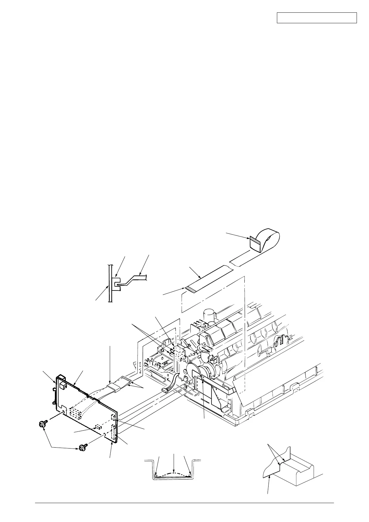
3.3.9 Carriage Cable
(1) Remove the printhead (see 3.3.1).
(2) Remove the upper cover (see 3.3.4 (1) – (5)).
(3) Remove the gear case Assy (see 3.3.5).
(4) Remove the space motor (see 3.3.7).
(5) Remove the space rack (3.3.8).
(6) Remove two screws 1, release the driver board 2 by lifting clamp 8, and disconnect cable
from connector 3, 4, 5, 6.
(7) Remove carriage cable 7 from fasteners on frame.
(8) To install, follow the removal steps in the reverse order.
Note on installation:
(1) Take care not to fold the carriage cable 7 during installation. Curve slightly the carriage
cable 7 when assembling into the fasteners.
(2) Make sure that the paper end lever 0 will not contact the Paper end Sensor 9 when
mounting the Driver Board.
(3) Make sure that there is not any dust or oil on the connector contact sections A to D. If
it is found, wipe it off by alcohol.
(4) Butt and attach the drive board 2 to the E sections (2 places) of the convex of the main
chassis.
0
2
7
8
6
9
2
5
1
4
3
7
ClawClaw
2
Butt to E sections
(2 places)
(at USB Ver.)
(at USB Ver.)