42089201TH Rev.4 68 /
Oki Data CONFIDENTIAL
A
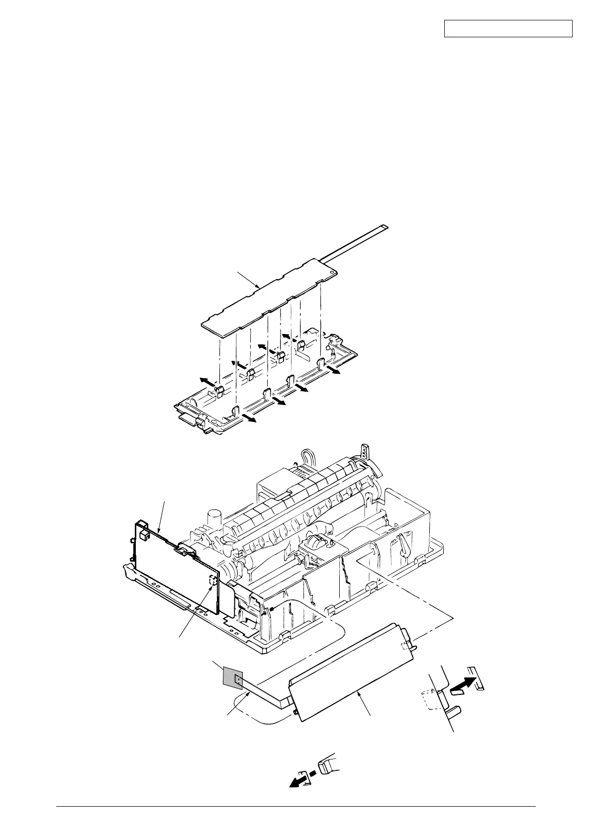
3.3.14 Operation Panel PCB (LEOP)
(1) Remove the upper cover (see 3.3.4 (1) – (5)).
(2) Disconnect the cable 1 from connector 3 of Driver board 2.
(3) Disengage claws on both sides from the frame, and remove the operation panel 4.
(4) Open claws (8 places) and remove the operation panel PCB 5 from the operation panel
4.
(5) To install, follow the removal steps in the reverse order.
Notes on installation
(1) Make sure that there is not any dust or oil on the connector contact section A. If it is
found, wipe it off by alcohol.
5
2
3
1
4