NOTE: If using remote sensors and the does not recognize the
sensor upon power up (displays a sensor fault), check the placement of this
jumper. If the jumper J1 is on terminals 1-2, move the jumper to terminals 2-
3.
For digital ModBus signal and power use a minimum of 4 conductors #18
AWG (0.9 mm²) insulated and shielded cable.
Shielding from either the controller or remote sensors should be bonded to
the enclosure screw located inside the .
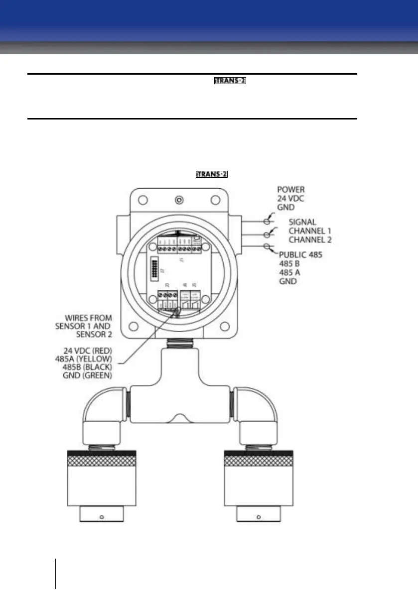
Figure 4-6 Wiring Diagram for Dual On-board Sensors