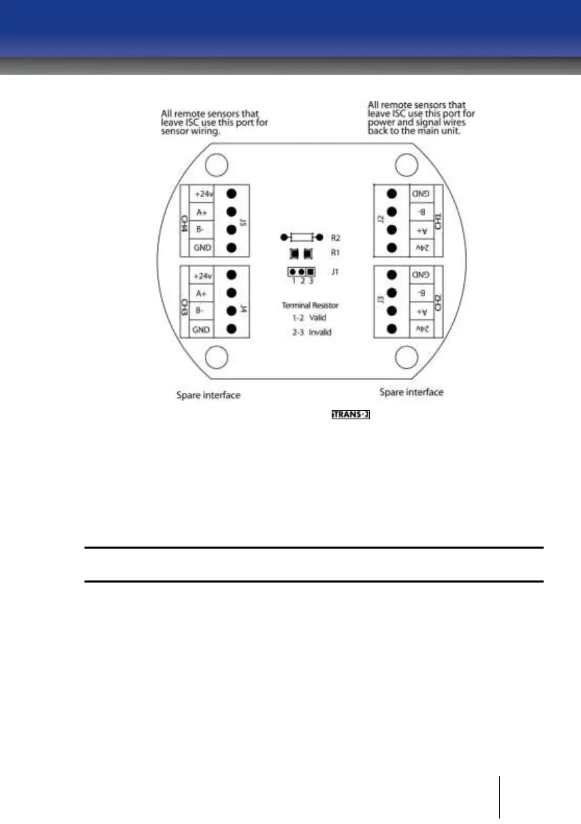
Figure A - 3 Electronics Board for Remote Sensor Unit
Installation
For details please see Chapter 3 |.
System Wiring
For details please see Chapter 4 |.
IMPORTANT: In Chapter 4 |, the “Power and Output Wiring (J1)” section is
replaced with the following section.
Power and Output Wiring (J1)
In most applications the power is supplied from the controller that is
receiving the 4-20mA output. In these applications only three wires are
required in case of single sensor unit and only four wires are required in
case of dual sensor unit since common is shared.
If the 4-20mA output is going to another device other than the one that is
powering it, or the transmitter has its own local power supply, another
connection from GND must be extracted for the 4-20mA loop to function.