Chapter 6 | Modbus Interface
Introduction
IMPORTANT: The device with public Modbus interface can also be
configured to operate with a MX43 controller from Oldham. Please follow the
procedure given below to enable MX43-compatibility mode on .
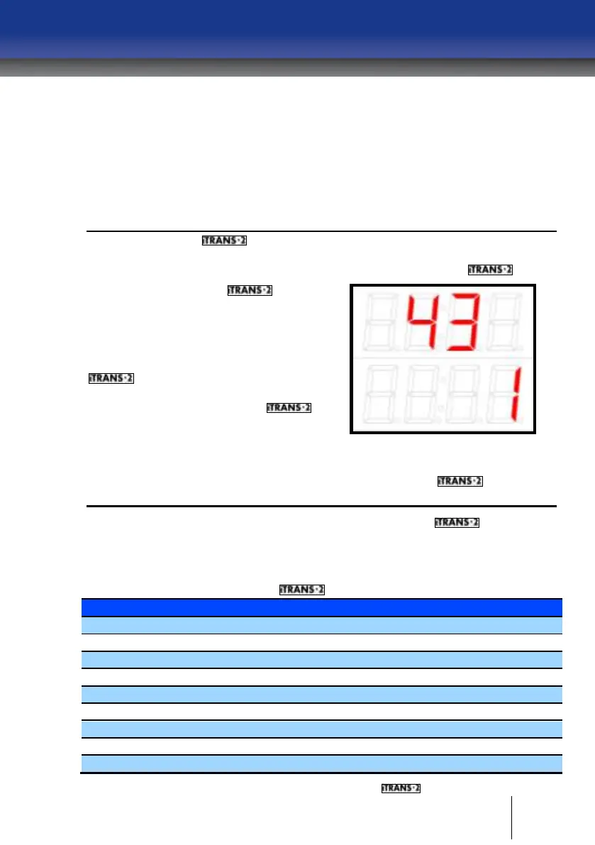
Set the Modbus ID of using
dip-switches as shown in Figure
4-10 according to MX43
configuration (for details please see
the user manual of MX43 controller).
The MX43-compatibility menu on
is password protected. To
enter MX43-compatibility menu,
remove the front cover of
and press “Enter” key. The access
code is “Enter”, “Up”, “Down”,
“Up”, “Mode”.
Figure 6-1 MX43-compatibilty Menu
Once the correct access code has been entered then the user can select to
enable (1) or disable (0) the MX43-compatibility mode on using “Up”
or “Down” key then the selection is confirmed by pressing the “Enter” key.
When programming the ModBus ID address on the electronics
module or on the smart sensor board, use the binary reference chart on the
following page. A “1” represents “ON” on the switch bank, and position 1 of
the switch bank represents the right most binary digit (LSB).
ModBus characteristics for the are listed below.
Table 6-1 ModBus Characteristics for the Gas Monitor