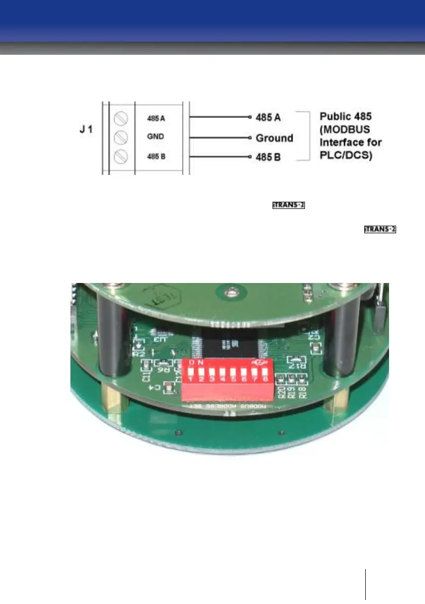
signals are wired into the RS485A and RS485B terminals on the board. See
Figure 4-9.
Figure 4-9 Wiring Diagram for the ModBus Interface
Setting the ModBus Address on the
Located on the back of the electronics module is an 8-position DIP switch.
This switch bank is used to set the ModBus Slave Address for the
unit. The address can be set from 1 to 255. Use the DIP switches to set the
binary representation of the desired address. 1 is bit zero, and 8 is bit 7. ON
represents a 1, and OFF represents zero. Refer to Appendix B for hex-to-
decimal equivalents.
Figure 4-10 Switch Bank for Setting ModBus Slave Address